Nissan Sentra Service Manual: Can communication circuit
Diagnosis procedure
1.Connector inspection
- Turn the ignition switch OFF.
- Disconnect the battery cable from the negative terminal.
- Disconnect all the unit connectors on can communication system.
- Check terminals and connectors for damage, bend and loose connection.
Is the inspection result normal? Yes >> go to 2.
No >> repair the terminal and connector.
2.Check harness continuity (short circuit)
Check the continuity between the data link connector terminals.

Is the inspection result normal? Yes >> go to 3.
No >> check the harness and repair the root cause.
3.Check harness continuity (short circuit)
Check the continuity between the data link connector and the ground.

Is the inspection result normal? YES >> GO TO 4.
NO >> Check the harness and repair the root cause.
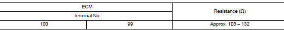
4.Check ecm and bcm termination circuit
- Remove the ecm and the bcm.
- Check the resistance between the ecm terminals.
- Check the resistance between the bcm terminals.

Is the measurement value within the specification? YES >> GO TO 5.
NO >> Replace the ECM and/or the BCM.
5.Check symptom
Connect all the connectors. Check if the symptoms described in the “symptom (results from interview with customer)” are reproduced.
Inspection result
Reproduced>>go to 6.
Non-reproduced>>start the diagnosis again. Follow the trouble diagnosis procedure when past error is detected.
6.Check unit reproduction
Perform the reproduction test as per the following procedure for each unit.
- Turn the ignition switch off.
- Disconnect the battery cable from the negative terminal.
- Disconnect one of the unit connectors of can communication system.
Note:
Ecm and bcm have a termination circuit. Check other units first.
- Connect the battery cable to the negative terminal. Check if the symptoms described in the “symptom (results from interview with customer)” are reproduced.
Note:
Although unit-related error symptoms occur, do not confuse them with other symptoms.
Inspection result
Reproduced>>connect the connector. Check other units as per the above procedure.
Non-reproduced>>replace the unit whose connector was disconnected.
 BCM branch line circuit
Diagnosis procedure
1.Check connector
Turn the ignition switch off.
Disconnect the battery cable from the negative terminal.
Check the terminals and connectors of the bcm for damage, bend and ...
 Can system (type 5)
Dtc/circuit diagnosis ...
Other materials:
Replacing
Replace the wiper blades if they are worn.
To replace the windshield wiper blades, follow
the procedure below:
When ignition switch is ON or within
60 seconds after placing the ignition switch
from ON to OFF position.
Quickly push the windshield wiper and
washer lever to the mist pos ...
G Sensor
Exploded View
G sensor
Bracket
Vehicle front
NВ·m (kg-m, ft-lb)
NВ·m (kg-m, in-lb)
Removal and Installation
WARNING:
Do not leave any objects (screwdrivers, tools, etc.) on the seat during
seat repair. It can lead to personal
injury if the side air bag module should acc ...
Wiring diagram
Manual air conditioning system
Wiring Diagram
Manual heater system
Wiring Diagram
...
