Nissan Sentra Service Manual: Daytime light relay circuit
Description
The bcm sends a daytime light request to the ipdm e/r via the can communication lines. The power flows through fuse 29 located in fuse block j/b to the daytime light relay coil. When the ipdm e/r operates the daytime light relay, power is sent to the daytime lamps.
Diagnosis procedure
Regarding Wiring Diagram information, refer to EXL-38, "Wiring Diagram".
1.Check daytime light relay voltage supply
- Turn the ignition switch off.
- Remove the daytime light relay.
- Check the voltage between the daytime light relay harness connector and ground.

Is the inspection result normal? Yes >> go to 3.
No >> go to 2.
2.Check daytime light relay fuse
Check that the following fuses are not blown.

Is the fuse blown? Yes >> replace the blown fuse after repairing the affected circuit.
No >> repair or replace the harness or connector.
3.Check daytime light relay control circuit
- Check continuity between the IPDM E/R harness connector and the daytime light relay harness connector.

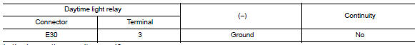
- Check continuity between the daytime light relay harness connector and ground.

Is the inspection result normal? Yes >> go to 4.
No >> repair or replace the harness or connector.
4.Check daytime light relay
Check the daytime light relay. Refer to exl-93, "component inspection".
Is the inspection result normal? YES >> GO TO 5.
NO >> Replace relay.
5.Check daytime light circuit (open or short to ground)
- Check continuity between the daytime light relay harness connector and the front combination lamp harness connector.

- Check continuity between the daytime light relay harness connector and ground.
Is the inspection result normal? Yes >> go to 6.
No >> repair or replace the harness or connector.
6.Check daytime light ground circuit for open
- Disconnect front combination lamp connector in question.
- Check continuity between the front combination lamp connector and ground.

Is the inspection result normal? Yes >> inspect daytime light bulb.
No >> repair or replace the harness or connector.
Component inspection
1. Check daytime light relay
- Turn ignition switch off.
- Remove daytime light relay.
- Check the continuity between daytime light relay terminals 3 and 5 when voltage is supplied between terminals 1 and 2.

Is the inspection result normal? Yes >> inspection end.
No >> replace daytime light relay.
 Headlamp (lo) circuit
Description
The ipdm e/r (intelligent power distribution module engine room) controls the
headlamp low relay based on
inputs from the bcm over the can communication lines. When the headlamp low
...
 Front fog lamp circuit
Description
The ipdm e/r (intelligent power distribution module engine room) controls the
front fog lamp relay based on
inputs from the bcm over the can communication lines. When the front fog lam ...
Other materials:
System description
Component parts
Component parts location
Ipdm e/r
System
Relay control system
Relay control system : system diagram
Relay control system : system description
Description
IPDM E/R activates the internal control circuit to perform the relay ON-OFF
control according to the input ...
P0743 Torque converter
DTC Logic
DTC DETECTION LOGIC
DTC
CONSULT screen terms
(Trouble diagnosis content)
DTC detection condition
Possible causes
P0743
TORQUE CONVERTER
(Torque Converter Clutch Circuit
Electrical)
The TCM torque converter clutch solenoid
valve current monitor ...
C1704, C1705, C1706, C1707 Low tire pressure
DTC Logic
NOTE:
The Signal Tech II Tool (J-50190) can be used to perform the following
functions. Refer to the Signal Tech II
User Guide for additional information.
Activate and display TPMS transmitter IDs
Display tire pressure reported by the TPMS transmitter
Read TPMS DTCs
Register ...
