Nissan Sentra Service Manual: Dtc/circuit diagnosis
Power supply and ground circuit
Audio unit
AUDIO UNIT : Diagnosis Procedure
Regarding wiring diagram information, refer to av-88, "wiring diagram".
1.Check fuse
Check that the following fuses are not blown.

Are the fuses blown? Yes >> replace the blown fuse after repairing the affected circuit.
No >> go to 2.
2.Check power supply circuit
- Turn ignition switch off.
- Disconnect audio unit connector m92.
- Check voltage between audio unit connector M92 and ground.

Is the inspection result normal? YES >> GO TO 3.
NO >> Repair or replace harness or connectors.
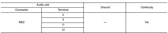
3.Check ground circuit
- Turn ignition switch off.
- Disconnect audio unit connector M93.
- Check continuity between audio unit connectors and ground.

Is the inspection result normal? Yes >> inspection end.
No >> repair or replace harness or connectors.
BluetoothВ® control unit
BLUETOOTHВ® CONTROL UNIT : Diagnosis Procedure
Regarding Wiring Diagram information, refer to AV-88, "Wiring Diagram".
1.Check fuse
Check that the following fuses are not blown.

Are the fuses blown? Yes >> replace the blown fuse after repairing the affected circuit.
No >> go to 2.
2.Check power supply circuit
- Turn ignition switch OFF.
- Disconnect bluetoothВ® control unit connector m45.
- Check voltage between bluetoothВ® control unit connector m45 and ground.

Is the inspection result normal? Yes >> go to 3.
No >> repair or replace harness or connectors.
3.Check ground circuit
- Turn ignition switch off.
- Check continuity between bluetoothВ® control unit connector m45 and ground.

Is the inspection result normal? YES >> Inspection End.
NO >> Repair or replace harness or connectors.
Front door speaker
Diagnosis procedure
Regarding Wiring Diagram information, refer to AV-88, "Wiring Diagram".
1.Connector check
Check the audio unit and speaker connectors for the following:
- Proper connection
- Damage
- Disconnected or loose terminals
Is the inspection result normal? Yes >> go to 2
NO >> Repair the terminals or connectors.
2.Check front door speaker signal circuit continuity
- Disconnect audio unit connector m92 and suspect front door speaker connector.
- Check continuity between audio unit connector m92 and suspect front door speaker connector.

- Check continuity between audio unit connector M92 and ground.
Is the inspection result normal? YES >> GO TO 3
NO >> Repair or replace harness or connectors.
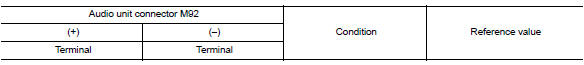
3.Check front door speaker signal
- Connect audio unit connector m92 and suspect front door speaker connector.
- Turn ignition switch to acc.
- Push audio unit power switch.
- Check signal between the terminals of audio unit connector M92.

Is the inspection result normal? Yes >> replace front door speaker. Refer to av-124, "removal and installation".
No >> replace audio unit. Refer to av-122, "removal and installation".
Front tweeter
Diagnosis procedure
Regarding Wiring Diagram information, refer to AV-88, "Wiring Diagram".
1.Connector check
Check the audio unit and speaker connectors for the following:
- Proper connection
- Damage
- Disconnected or loose terminals
Is the inspection result normal? YES >> GO TO 2
No >> repair the terminals or connectors.
2.Check front tweeter signal circuit continuity
- Disconnect audio unit connector M92 and suspect front tweeter connector.
- Check continuity between audio unit connector m92 and suspect front tweeter connector.

- Check continuity between audio unit connector M92 and ground.

Is the inspection result normal? Yes >> go to 3
No >> repair or replace harness or connectors.
3.Check front tweeter signal
- Connect audio unit connector m92 and suspect front tweeter connector.
- Turn ignition switch to ACC
- Push audio unit POWER switch.
- Check signal between the terminals of audio unit connector m92.


Is the inspection result normal? Yes >> replace front tweeter. Refer to av-123, "removal and installation".
No >> replace audio unit. Refer to av-122, "removal and installation".
Rear speaker
Diagnosis procedure
Regarding Wiring Diagram information, refer to AV-88, "Wiring Diagram".
1.Connector check
Check the audio unit and speaker connectors for the following:
- Proper connection
- Damage
- Disconnected or loose terminals
Is the inspection result normal? YES >> GO TO 2
No >> repair the terminals or connectors.
2.Check rear speaker signal circuit continuity
- Disconnect audio unit connector m92 and suspect rear speaker connector.
- Check continuity between audio unit connector M92 and suspect rear speaker connector.

- Check continuity between audio unit connector M92 and ground.

Is the inspection result normal? Yes >> go to 3
No >> repair or replace harness or connectors.
3.Check rear speaker signal
- Connect audio unit connector m92 and suspect rear speaker connector.
- Turn ignition switch to acc.
- Push audio unit power switch.
- Check signal between the terminals of audio unit connector m92.


Is the inspection result normal? Yes >> replace rear speaker. Refer to av-125, "removal and installation".
No >> replace audio unit. Refer to av-122, "removal and installation".
BluetoothВ® voice signal circuit
Diagnosis procedure
Regarding wiring diagram information, refer to av-88, "wiring diagram".
1.Check bluetoothВ® voice signal circuit continuity
- Turn ignition switch off.
- Disconnect audio unit connector m93 and bluetoothВ® control unit connector m45.
- Check continuity between audio unit connector M93 and BluetoothВ® control unit connector M45.

- Check continuity between audio unit connector M93 and ground.

Is inspection result normal? Yes >> go to 2.
No >> repair or replace harness or connectors.
2.Check bluetoothВ® voice signal ground circuit continuity
Check continuity between audio unit connector m93 and bluetoothВ® control unit connector m45.

Is inspection result normal? Yes >> go to 3.
No >> repair or replace harness or connectors.
3.Check bluetoothВ® voice signal
- Connect audio unit connector M93 and BluetoothВ® control unit connector M45.
- Turn ignition switch to acc.
- Press
 switch.
 - Check signal between the terminals of audio unit connector M93.

Is the inspection result normal? Yes >> replace bluetoothВ® control unit. Refer to av-134, "removal and installation".
No >> replace audio unit. Refer to av-122, "removal and installation".
BluetoothВ® control signal circuit
Diagnosis procedure
Regarding wiring diagram information, refer to av-88, "wiring diagram".
1.Check control signal circuit continuity
- Turn ignition switch off
- Disconnect BluetoothВ® control unit connector M45.
- Check continuity between bluetoothВ® control unit connector m45 and ground.

Is the inspection result normal? YES >> Replace BluetoothВ® control unit. Refer to AV-134, "Removal and Installation".
NO >> Repair or replace harness or connectors.
Microphone signal circuit
Diagnosis Procedure
Regarding wiring diagram information, refer to av-88, "wiring diagram".
1.Check harness between bluetoothВ® control unit and microphone
- Turn ignition switch off.
- Disconnect bluetoothВ® control unit connector m45 and microphone connector r4.
- Check continuity between BluetoothВ® control unit connector M45 and microphone connector R4.

- Check continuity between BluetoothВ® control unit connector M45 and ground.

Are continuity results as specified? Yes >> go to 2
NO >> Repair harness or connectors.
2.Check microphone power supply
- Connect bluetoothВ® control unit connector m45 and microphone connector r4.
- Turn ignition switch on.
- Check voltage between microphone connector r4 and ground.

Is the voltage reading as specified? Yes >> go to 3
No >> replace bluetoothВ® control unit. Refer to av-134, "removal and installation".
3.Check microphone signal
Check signal between terminals of BluetoothВ® control unit connector M45.

Were voltage readings as specified? Yes >> replace bluetoothВ® control unit. Refer to av-134, "removal and installation".
No >> replace microphone. Refer to av-135, "removal and installation".
Steering switch
Diagnosis procedure
Regarding wiring diagram information, refer to av-88, "wiring diagram".
1.Check steering wheel audio control switch resistance
- Turn ignition switch OFF.
- Disconnect combination switch (spiral cable) connector m79.
- Check resistance between the terminals of combination switch (spiral cable) connector m79.

Is the inspection result normal? YES >> GO TO 2.
NO >> Replace steering switches. Refer to AV-208, "Removal and Installation".
2.Check harness between bluetoothВ® control unit and combination switch (spiral cable)
- Disconnect bluetoothВ® control unit connector m45 and combination switch (spiral cable) connector m80.
- Check continuity between bluetoothВ® control unit connector m45 and combination switch (spiral cable) connector m80.

- Check continuity between BluetoothВ® control unit connector M45 and ground.

Is the inspection result normal? Yes >> go to 3.
NO >> Repair or replace harness or connectors.
3.Check combination switch (spiral cable)
Check continuity between combination switch (spiral cable) connectors m79 and m80.

Is the inspection result normal? Yes >> go to 4.
No >> replace combination switch (spiral cable). Refer to sr-16, "removal and installation".
4.Check harness between bluetoothВ® control unit and audio unit
- Disconnect audio unit connector M92.
- Check continuity between BluetoothВ® control unit connector M45 and audio unit connector M92.

- Check continuity between BluetoothВ® control unit connector M45 and ground.

Is the inspection result normal? Yes >> replace audio unit. Refer to av-203, "removal and installation".
No >> repair or replace harness or connectors.
Usb connector
Diagnosis Procedure
Regarding Wiring Diagram information, refer to AV-88, "Wiring Diagram".
1.Check usb interface harness continuity
- Turn ignition switch off.
- Disconnect audio unit connector m97 and usb interface connector m132.
- Check continuity between audio unit connector m97 and usb interface connector m132.
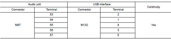
- Check continuity between audio unit connector M97 and ground.

Is the inspection result normal? YES >> Replace the USB interface. Refer to AV-132, "Removal and Installation".
NO >> Repair or replace harness or connectors.
 Basic inspection
Diagnosis and repair workflow
Work Flow
Overall sequence
Detailed flow
1.Get information for symptom
Get detailed information from the customer about the symptom (the condition
and the envi ...
 Symptom diagnosis
Audio system
Symptom table
Related to audio
Related to hands-free phone
Before performing diagnosis, confirm that the cellular phone being used
by the customer is compatible with
t ...
Other materials:
Dtc/circuit diagnosis
Power supply and ground circuit
Audio unit
Audio unit : diagnosis procedure
Regarding wiring diagram information, refer to av-25, "wiring diagram".
1.Check fuse
Check that the following fuses are not blown.
Are the fuses blown?
Yes >> replace the blown fuse after repairing t ...
How to erase permanent DTC
Description
OUTLINE
When a DTC is stored in ECM
When a DTC is stored in ECM and MIL is ON, a permanent DTC is erased with MIL
shutoff if the same malfunction
is not detected after performing the driving pattern for MIL shutoff three times
in a raw.
*1: When the same malfunction is detec ...
Dtc/circuit diagnosis
U1000 can comm circuit
Description
Refer to LAN-7, "CAN COMMUNICATION SYSTEM : System Description".
Dtc logic
DTC DETECTION LOGIC
NOTE:
U1000 can be set if a module harness was disconnected and reconnected,
perhaps during a repair. Confirm
that there are actual CAN diagnostic sym ...
