Nissan Sentra Service Manual: Encoder
Driver side
DRIVER SIDE : Description
Detects condition of the front power window motor lh operation and transmits to main power window and door lock/unlock switch as pulse signal.
DRIVER SIDE : Component Function Check
1. Check encoder operation
Check front door glass lh perform auto open/close operation normally with main power window and door lock/unlock switch.
Is the inspection result normal? Yes >> encoder operation is ok.
No >> refer to pwc-50, "driver side : diagnosis procedure".
DRIVER SIDE : Diagnosis Procedure
Regarding wiring diagram information, refer to pwc-18, "wiring diagram".
Encoder circuit check
1. Check encoder operation
- Connect front power window motor lh.
- Turn ignition switch ON.
- Check signal between main power window and door lock/unlock switch connector d5 and ground with oscilloscope.

Is the inspection result normal? YES >> Check intermittent incident. Refer to GI-39, "Intermittent Incident".
NO >> GO TO 2.
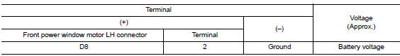
2. Check front power window motor lh power supply
- Turn ignition switch on.
- Check voltage between front power window motor lh connector d8 and ground.
Is the inspection result normal? YES >> GO TO 4.
NO >> GO TO 3.
3. Check harness continuity 1
- Turn ignition switch OFF.
- Disconnect main power window and door lock/unlock switch and front power window motor lh.
- Check continuity between main power window and door lock/unlock switch connector D5 and front power window motor connector D8.

- Check continuity between main power window and door lock/unlock switch connector d5 and ground.

Is the inspection result normal? YES >> Replace main power window and door lock/unlock switch. Refer to PWC-70, "Removal and Installation".
After that, refer to PWC-29, "Work Procedure".
NO >> Repair or replace harness or connectors.
4. Check ground circuit
- Turn ignition switch off.
- Disconnect front power window motor LH.
- Check continuity between front power window motor lh connector d8 and ground.

Is the inspection result normal? Yes >> go to 6.
No >> go to 5.
5. Check harness continuity 2
- Disconnect main power window and door lock/unlock switch.
- Check continuity between main power window and door lock/unlock switch connector d5 and front power window motor lh connector d8.

Is the inspection result normal? YES >> Check main power window and door lock/unlock switch. Refer to PWC-36, "POWER WINDOW MAIN SWITCH : Component Inspection".
NO >> Repair or replace the harness or connectors.
6. Check harness continuity 3
- Disconnect main power window and door lock/unlock switch.
- Check continuity between main power window d5 and door lock/unlock switch connector and front power window motor lh connector d8.

- Check continuity between main power window and door lock/unlock switch connector d5 and ground.

Is the inspection result normal? Yes >> replace front power window motor lh. Refer to gw-16, "removal and installation". After that, refer to pwc-29, "work procedure".
No >> repair or replace harness or connectors.
DRIVER SIDE : Special Repair Requirement
1. Perform initialization procedure
Perform initialization procedure.
Refer to pwc-29, "work procedure".
Is the inspection result normal? Yes >> inspection end.
No >> check intermittent incident. Refer to gi-39, "intermittent incident".
 Power window motor
DRIVER SIDE
DRIVER SIDE : Description
Door glass moves up/down by receiving the signal from main power window and
door lock/unlock switch
DRIVER SIDE : Component Function Check
1. Check front po ...
 Door switch
With intelligent key
WITH INTELLIGENT KEY : Component Function Check
1.Check function
Select DOOR LOCK of BCM using CONSULT.
Select DOOR SW-DR, DOOR SW-AS, DOOR SW-RL and DOOR SW-RR in DATA M ...
Other materials:
Removal and installation
Av control unit
Exploded view
AV control unit
Av control unit bracket (lh)
AV control unit bracket (RH)
Removal and installation
Removal
Caution:
Remove battery terminal and av control unit after a lapse of 30
seconds or more after turning the
ignition switch off.
Before ...
Storage pouch
A storage pouch is located on the front of the
driver’s and passenger’s seats.
WARNING
Do not store angular, sharp, heavy objects
or objects that cannot fully fit inside
the pouch because they might increase
the likelihood of an injury in a
crash.
To ensure ...
Heater operation
This mode is used to direct heated air to the foot
outlets. Some air also flows from the defrost
outlets and the side vent outlets.
Press the button to the OFF
position
for normal heating.
Press the air flow control
button.
Turn the fan control dial to the desired position.
Tur ...
