Nissan Sentra Service Manual: Flywheel
Exploded View

- Flywheel
Removal and Installation
REMOVAL
- Remove the engine and the transaxle assembly from the vehicle, and separate the transaxle from the engine. Refer to TM-28, "Exploded View".
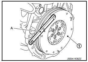
- Remove flywheel.
- Secure flywheel (1) using Tool (A), and remove bolts using suitable tool.
Tool number : KV11105210 (J-44716)

CAUTION:
- Do not disassemble flywheel.
- Do not place flywheel with signal plate facing down.
- When handling signal plate, take care not to damage or scratch.
- Handle signal plate, do so in a manner that prevents it from becoming magnetized.
INSTALLATION
- Install flywheel.
- Secure flywheel (1) using Tool (A), and install bolts.
Tool number : KV11105210 (J-44716)
CAUTION:
Be careful not to damage or scratch the contact surface of flywheel.
Inspection
FLYWHEEL DEFLECTION
- Measure the deflection of flywheel contact surface to torque with a dial indicator (A).
- Measure the deflection at 210 mm (8.27 in) diameter.
Limit : 0.45 mm (0.0177 in) or less.

- If measured value is out of the standard, replace flywheel.
- If a trace of burn or discoloration is found on the surface, repair it with sandpaper.
MOVEMENT AMOUNT OF FLYWHEEL
CAUTION:
Do not disassemble double mass flywheel.
Movement Amount of Thrust (Fore-and-Aft) Direction
- Measure the movement amount of thrust (fore-and-aft) direction when 100 N (10.2 kg, 22 lb) force is added at the portion of 125 mm (4.92 in) radius from the center of flywheel.
Standard : 1.8 mm (0.071 in) or less
- If measured value is out of the standard, replace flywheel
Movement Amount in Radial (Rotation) Direction
Check the movement amount of radial (rotation) direction with the following procedure:
- Install clutch cover bolt (1) to clutch cover hole, and place a torque wrench (A) on the extended line of the flywheel (2) center line.
- Tighten bolt at a force of 9.8 NВ·m (1.0 kg-m, 87 in-lb) to keep it from loosening.
- Put a mating mark on circumferences of the two flywheel masses without applying any load (Measurement standard points).
- Apply a force of 9.8 NВ·m (1.0 kg-m, 87 in-lb) in each direction, and mark the movement amount on the mass on the transaxle side.
- Measure the dimensions of movement amounts (A) and (B) on circumference of the flywheel on the transaxle side.
Limit : 33.2 mm (1.307 in) or less.

- If measured value is out of the standard, replace flywheel.

 Drive plate
Exploded View
Pilot converter
Drive plate
Reinforcement plate
Chamfered
Removal and Installation
REMOVAL
Remove the engine and the transaxle assembly from the vehicle, and
...
Other materials:
Main line between ipdm-e and dlc circuit
Diagnosis procedure
1.Check connector
Turn the ignition switch off.
Disconnect the battery cable from the negative terminal.
Check the following terminals and connectors for damage, bend and loose
connection (connector side
and harness side).
Harness connector e4
Harness connec ...
Ecm branch line circuit
Diagnosis procedure
1.Check connector
Turn the ignition switch off.
Disconnect the battery cable from the negative terminal.
Check the terminals and connectors of the ecm for damage, bend and loose
connection (unit side and
connector side).
Is the inspection result normal?
YES > ...
B142A Ignition voltage
Description
DTC B142A IGNITION VOLTAGE
Ignition voltage is supplied to the air bag diagnosis sensor unit when the
ignition is in the ON position. The air
bag diagnosis sensor unit will monitor for low or high ignition voltage.
PART LOCATION
Refer to SRC-5, "Component Parts Location" ...
