Nissan Sentra Service Manual: Front stabilizer
Exploded View
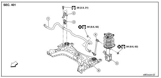
- Stabilizer bar
- Stabilizer clamp
- Stabilizer bushing
- Stabilizer connecting rod
- Front coil spring and strut
- Front suspension member
 Front
Front
Removal and Installation
REMOVAL
- Remove the wheel and tire using power tool. Refer to WT-47, "Exploded View".
- Remove the nut and disconnect the stabilizer connecting rod from the stabilizer bar.
- Remove the front suspension member. Refer to FSU-16, "Removal and Installation".
- Remove the stabilizer clamp bolts (
 ).
). - Remove the stabilizer clamps.
- Remove the stabilizer bushings.
- Remove the stabilizer bar.
- Inspect the components. Refer to FSU-13, "Inspection".

INSTALLATION
Installation is in the reverse order of removal.
- Install the stabilizer bushing with the slit (B) facing toward the front
of the vehicle (
 ).
). - Install the stabilizer clamp with oblong hole (A) facing toward the
front of the vehicle (
 ).
).

- Install the stabilizer clamp bolts in the order of 1 to 5 as shown.
Manual tightening : 1
Temporary tightening : 2 → 3
Final tightening (Specified torque) : 4 → 5
 : Front

- To connect the stabilizer connecting rod (1), tighten the nut while holding the hexagonal part (A) on the stabilizer connecting rod.
CAUTION:
Do not reuse stabilizer connecting rod nuts.

- Perform the final tightening of the nuts and bolts under unladen conditions with the tires on level ground.
- Complete the inspection. Refer to FSU-13, "Inspection".
Inspection
INSPECTION AFTER REMOVAL
Check the stabilizer bar, the stabilizer connecting rods, the stabilizer bushings, and the stabilizer clamps for deformation, cracks or damage. Replace components if necessary.
INSPECTION AFTER INSTALLATION
- Check the neutral position of the steering angle sensor. Refer to BRC-54, "Work Procedure".
- Check the wheel alignment. Refer to FSU-6, "Inspection".
 Transverse link
Exploded View
Upper link
Front suspension member
Transverse link
Front
Removal and Installation
REMOVAL
Remove the wheel and tire using power tool. Refer to WT-47, "Explode ...
 Steering knuckle
Exploded View
Steering knuckle
Splash guard
Wheel stud
Wheel hub and bearing
Disc brake rotor
Wheel hub lock nut
Nut retainer
Cotter pin
Removal and Installation
REMOVAL
...
Other materials:
Vehicle recovery (freeing a stuck vehicle)
Front (if so equipped)
Do not use the hook to tow the vehicle.
Remove the cover bumper bracket using a
flat screwdriver or any flat tool.
To protect the bumper body, place a piece of
cloth between the tool and the vehicle.
The tool used should be inserted by the
lower portion of t ...
Front wiper motor lo circuit
Component function check
1. Check front wiper lo operation
Ipdm e/r auto active test
Start ipdm e/r auto active test. Refer to pcs-9, "diagnosis description"
(with intelligent key system) or
pcs-37, "diagnosis description" (without intelligent key system).
Check tha ...
C1120, C1122, C1124, C1126 ABS In valve system
DTC Logic
Dtc detection logic
DTC
Display Item
Malfunction detected condition
Possible causes
C1120
FR LH IN ABS SOL
When a malfunction is detected in front LH ABS IN
valve.
Harness or connector
ABS actuator and electric unit
(control unit)
...
