Nissan Sentra Service Manual: P1572 ASCD Brake switch
DTC Logic
DTC DETECTION LOGIC
NOTE:
- If DTC P1572 is displayed with DTC P0605, first perform the trouble diagnosis for DTC P0605. Refer to EC-348, "DTC Logic".
- This self-diagnosis has the one trip detection logic. When
malfunction A is detected, DTC is not
stored in ECM memory. And in that case, 1st trip DTC and 1st trip freeze
frame data are displayed.
1st trip DTC is erased when ignition switch OFF. And even when malfunction A is detected in two consecutive trips, DTC is not stored in ECM memory.
| DTC No. | CONSULT screen terms (Trouble diagnosis content) | DTC detecting condition | Possible cause | |
| P1572 | ASCD BRAKE SW (ASCD BRAKE SW) | A) | When the vehicle speed is above 30 km/ h (19 MPH), ON signals from the stop lamp switch and the brake pedal position switch are sent to the ECM at the same time. |
|
| B) | Brake pedal position switch signal is not sent to ECM for extremely long time while the vehicle is driving. | |||
DTC CONFIRMATION PROCEDURE
1.PRECONDITIONING
If DTC Confirmation Procedure has been previously conducted, always perform the following procedure before conducting the next test.
- Turn ignition switch OFF and wait at least 10 seconds.
- Turn ignition switch ON.
- Turn ignition switch OFF and wait at least 10 seconds.
NOTE:
Procedure for malfunction B is not described here. It takes extremely long time to complete procedure for malfunction B. By performing procedure for malfunction A, the incident that causes malfunction B can be detected.
>> GO TO 2.
2.PERFORM DTC CONFIRMATION PROCEDURE FOR MALFUNCTION A
- Start engine.
- Press MAIN switch and make sure that CRUISE indicator is displayed in combination meter.
- Drive the vehicle for at least 5 consecutive seconds as per the following conditions.
CAUTION:
Always drive vehicle at a safe speed.
NOTE:
This procedure may be conducted with the drive wheels lifted in the shop or by driving the vehicle.
If a road test is expected to be easier, it is unnecessary to lift the vehicle.

- Check DTC.
Is DTC detected? YES >> Proceed to EC-397, "Diagnosis Procedure".
NO >> GO TO 3.
3.PERFORM DTC CONFIRMATION PROCEDURE FOR MALFUNCTION B
- Drive the vehicle for at least 5 consecutive seconds as per the following conditions.
CAUTION:
Always drive vehicle at a safe speed.
NOTE:
This procedure may be conducted with the drive wheels lifted in the shop or by driving the vehicle.
If a road test is expected to be easier, it is unnecessary to lift the vehicle.

- Check DTC.
Is DTC detected? YES >> Proceed to EC-397, "Diagnosis Procedure".
NO >> INSPECTION END
Diagnosis Procedure
1.CHECK OVERALL FUNCTION-1
 With CONSULT
- Turn ignition switch ON.
- Select “BRAKE SW1” in “DATA MONITOR” mode of “ENGINE” using CONSULT.
- Check “BRAKE SW1” indication as per the following conditions.

 Without CONSULT
- Turn ignition switch ON.
- Check the voltage between ECM harness connector terminals as per the following.

Is the inspection result normal? YES >> GO TO 2.
NO >> MT models: GO TO 3.
>> CVT models: GO TO 4.
2.CHECK OVERALL FUNCTION-2
 With CONSULT
Select “BRAKE SW2” and check indication as per the following conditions.

 Without CONSULT
Check the voltage between ECM harness connector terminals as per the following conditions.

Is the inspection result normal? YES >> Check intermittent incident. Refer to GI-39, "Intermittent Incident".
NO >> GO TO 7.
3.CHECK CLUTCH PEDAL POSITION SWITCH POWER SUPPLY
- Turn ignition switch OFF.
- Disconnect clutch pedal position switch harness connector.
- Turn ignition switch ON.
- Check the voltage between clutch pedal position switch harness connector and ground.

Is the inspection result normal? YES >> GO TO 4.
NO >> Perform the trouble diagnosis for power supply circuit.
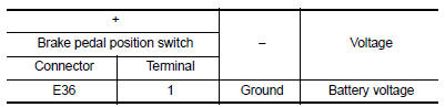
4.CHECK BRAKE PEDAL POSITION SWITCH POWER SUPPLY
- Turn ignition switch OFF.
- Disconnect brake pedal position switch harness connector
- Turn ignition switch ON.
- Check the voltage between brake pedal position switch harness connector and ground.
Is the inspection result normal? YES >> GO TO 5.
NO >> Perform the trouble diagnosis for power supply circuit.
5.CHECK BRAKE PEDAL POSITION SWITCH INPUT SIGNAL CIRCUIT
- Turn ignition switch OFF.
- Disconnect ECM harness connector.
- Check the continuity between brake pedal position switch harness connector and ECM harness connector.

- Also check harness for short to ground and to power.
Is the inspection result normal?
YES >> GO TO 6.
NO >> Repair or replace error-detected parts.
6.CHECK BRAKE PEDAL POSITION SWITCH
Check the brake pedal position switch. Refer to EC-394, "Component Inspection (Brake Pedal Position Switch)" Is the inspection result normal? YES >> Check intermittent incident. Refer to GI-39, "Intermittent Incident".
NO >> Replace brake pedal position switch. Refer to BR-22, "Exploded View".
7.CHECK STOP LAMP SWITCH POWER SUPPLY CIRCUIT
- Turn ignition switch OFF.
- Disconnect stop lamp switch harness connector
- Check the voltage between stop lamp switch harness connector and ground.

Is the inspection result normal? YES >> GO TO 8.
NO >> Perform the trouble diagnosis for power supply circuit.
8.CHECK STOP LAMP SWITCH GROUND CIRCUIT
- Disconnect stop lamp relay harness connector.
- Check the continuity between stop lamp switch harness connector and ECM harness connector.

- Also check harness for short to ground and to power.
Is the inspection result normal? YES >> GO TO 9.
NO >> Repair or replace error-detected parts.
9.CHECK STOP LAMP SWITCH
Check the stop lamp switch. Refer to EC-395, "Component Inspection (Stop Lamp Switch)".
Is the inspection result normal? YES >> Check intermittent incident. Refer to GI-39, "Intermittent Incident".
NO >> Replace stop lamp switch. Refer to BR-22, "Exploded View".
Component Inspection (Brake Pedal Position Switch)
1.CHECK BRAKE PEDAL POSITION SWITCH-1
- Turn ignition switch OFF.
- Disconnect brake pedal position harness connector.
- Check the continuity between brake pedal position switch terminals as per the following conditions.

Is the inspection result normal? YES >> INSPECTION END
NO >> GO TO 2.
2.CHECK BRAKE PEDAL POSITION SWITCH-2
- Adjust brake pedal position switch installation. Refer to BR-15, "Adjustment".
- Check the continuity between brake pedal position switch terminals as per the following conditions.

Is the inspection result normal? YES >> INSPECTION END
NO >> Replace brake pedal position switch. Refer to BR-22, "Exploded View".
Component Inspection (Stop Lamp Switch)
1.CHECK STOP LAMP SWITCH-1
- Turn ignition switch OFF.
- Disconnect stop lamp switch harness connector.
- Check the continuity between stop lamp switch terminals as per the following conditions.

Is the inspection result normal? YES >> INSPECTION END
NO >> GO TO 2.
2.CHECK STOP LAMP SWITCH-2
- Adjust stop lamp switch installation. Refer to BR-15, "Adjustment".
- Check the continuity between stop lamp switch terminals as per the following conditions.

Is the inspection result normal? YES >> INSPECTION END
NO >> Replace stop lamp switch. Refer to BR-22, "Exploded View".
 P1564 ASCD Steering switch
DTC Logic
DTC DETECTION LOGIC
NOTE:
If DTC P1564 is displayed with DTC P0605, first perform the trouble
diagnosis for DTC P0605. Refer to
EC-348, "DTC Logic".
DTC No.
CONSUL ...
 P1574 ASCD Vehicle speed sensor
Description
The ECM receives two vehicle speed sensor signals via CAN communication line.
One is sent from combination
meter, and the other is from TCM (Transmission control module). The ECM uses ...
Other materials:
Washer fluid level switch circuit
Description
Transmits the washer level switch signal to the combination meter.
Diagnosis procedure
Regarding Wiring Diagram information, refer to MWI-28, "Wiring Diagram".
1.Check washer level switch signal circuit
Turn ignition switch off.
Disconnect combination meter connecto ...
Tire dressings
NISSAN does not recommend the use of tire
dressings. Tire manufacturers apply a coating to
the tires to help reduce discoloration of the rubber.
If a tire dressing is applied to the tires, it may
react with the coating and form a compound. This
compound may come off the tire while driving and ...
Precaution for Supplemental Restraint System (SRS) "AIR BAG" and "SEAT
BELT PRE-TENSIONER"
The Supplemental Restraint System such as “AIR BAG” and “SEAT BELT PRE-TENSIONER”,
used along
with a front seat belt, helps to reduce the risk or severity of injury to the
driver and front passenger for certain
types of collision. Information necessary to service the system ...
