Nissan Sentra Service Manual: P1586 G Sensor
DTC Logic
DTC DETECTION LOGIC
| DTC | CONSULT screen terms (Trouble diagnosis content) | DTC detection condition | Possible causes |
| P1586 | G Sensor (Gravity Sensor Circuit) | When the following diagnosis conditions are
satisfied and the detection conditions are satisfied
twice in the same DC: Diagnosis conditions
Detection condition
|
|
| When the following diagnosis conditions are satisfied and the detection conditions are satisfied twice in the same DC: Diagnosis conditions
Detection condition
|
NOTE:
DC stands for “DRIVING CYCLE” and indicates a series of driving cycle of “Ignition switch OFF → ON → driving → OFF”.
DTC CONFIRMATION PROCEDURE
CAUTION:
Be careful of the driving speed.
1.PREPARATION BEFORE WORK
If another “DTC CONFIRMATION PROCEDURE” occurs just before, turn ignition switch OFF and wait for at least 10 seconds, then perform the next test.
>> GO TO 2.
2.CHECK DTC DETECTION
 With CONSULT
- With CONSULT
- Drive the vehicle for 10 seconds or more.
- Stop the vehicle.
CAUTION:
Never stop the engine.
- Repeat step 2 through 3.
- Check the DTC.
Is “P1586” detected? YES >> Go to TM-218, "Diagnosis Procedure".
NO >> INSPECTION END
Diagnosis Procedure
1.CHECK G SENSOR SIGNAL
 With CONSULT
- Park the vehicle on a level surface.
- Turn ignition switch ON.
- Select “Data Monitor” in “TRANSMISSION”.
- Select “G SEN SLOPE”.
- Swing the vehicle and check if the value varies between −40.45% and 40.45%.

Is the inspection result normal? YES >> GO TO 2.
NO >> GO TO 3.
2.CALIBRATION OF G SENSOR (PART 1)
 With CONSULT
- Select “Self Diagnostic Results” in “TRANSMISSION”.
- Touch “Erase”.
>> Perform “CALIBRATION OF G SENSOR”. Refer to TM-147, "Work Procedure".
3.CHECK SENSOR POWER SUPPLY
- Turn ignition switch OFF.
- Disconnect G sensor connector.
- Turn ignition switch ON.
- Check voltage between G sensor harness connector terminal and ground.

Is the inspection result normal? YES >> GO TO 4.
NO >> GO TO 8.
4.CHECK CIRCUIT BETWEEN TCM AND G SENSOR (PART 1)
- Turn ignition switch OFF.
- Disconnect TCM connector.
- Check continuity between TCM harness connector terminals and G sensor harness connector terminals.

Is the inspection result normal? YES >> GO TO 5.
NO >> Repair or replace malfunctioning parts.
5.CHECK CIRCUIT BETWEEN TCM AND G SENSOR (PART 2)
Check continuity between TCM harness connector terminal and ground.

The inspection result normal? Yes >> go to 6.
No >> repair or replace malfunctioning parts.
6.Check g sensor
- Remove g sensor. Refer to tm-265, "removal and installation".
- Connect the all connectors.
- Turn ignition switch on.
- Check voltage between TCM connector terminal and ground.
 : Direction of gravitational
force

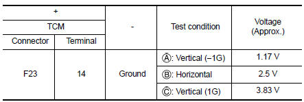
Is the inspection result normal? Yes >> go to 7.
No >> replace g sensor. Refer to tm-265, "removal and installation".
7.Calibration of g sensor (part 2)
 With CONSULT
- Install G sensor. Refer to TM-265, "Removal and Installation".
- Select “Self Diagnostic Results” in “TRANSMISSION”.
- Touch “Erase”.
>> Perform “CALIBRATION OF G SENSOR”. Refer to TM-147, "Work Procedure".
8.CHECK SENSOR POWER SUPPLY CIRCUIT (PART 1)
- Turn ignition switch OFF.
- Disconnect TCM connector.
- Check continuity between TCM harness connector terminal and G sensor harness connector terminal

Is the inspection result normal? YES >> GO TO 9.
NO >> Repair or replace malfunctioning parts.
9.CHECK SENSOR POWER SUPPLY CIRCUIT (PART 2)
Check continuity between TCM harness connector terminal and ground.

Is the inspection result normal? YES >> Check intermittent incident. Refer to GI-39, "Intermittent Incident".
NO >> Repair or replace malfunctioning parts.
 P099C Shift solenoid G
DTC Logic
DTC
CONSULT screen terms
(Trouble diagnosis content)
DTC detection condition
Possible causes
P099C
SHIFT SOLENOID G
(Shift Solenoid G Control Circuit
H ...
 P1588 G Sensor
DTC Logic
DTC DETECTION LOGIC
DTC
CONSULT screen terms
(Trouble diagnosis content)
DTC detection condition
Possible causes
P1588
G Sensor
(Gravity S ...
Other materials:
Both side headlamps do not switch
to high beam
Description
The headlamps (both sides) do not switch to high beam when the lighting
switch is in the hi or pass setting.
Diagnosis procedure
1.Combination switch (lighting and turn signal switch) inspection
Check the combination switch (lighting and turn signal switch). Refer to
bcs-72, &q ...
Rear disc brake
BRAKE PAD
BRAKE PAD : Exploded View
Upper sliding pin bolt
Lower sliding pin bolt
Bushing
Cylinder body
Inner shim cover
Inner shim
Inner pad (with pad wear sensor)
Pad retainer
Torque member
Outer pad
Outer shim
Outer shim cover
Apply rubber grease
Molykote A ...
System description
Component parts
Component parts location
Ipdm e/r
System
Relay control system
Relay control system : system diagram
Relay control system : system description
Description
IPDM E/R activates the internal control circuit to perform the relay ON-OFF
control according to the input ...
