Nissan Sentra Service Manual: Power supply and ground circuit
Combination meter
Combination meter : diagnosis procedure
Regarding Wiring Diagram information, refer to MWI-28, "Wiring Diagram".
1.Check fuses
Check that the following fuses are not blown.

Is the fuse blown? YES >> Replace the blown fuse after repairing the affected circuit.
NO >> GO TO 2.
2.Power supply circuit check
Check voltage between combination meter harness connector M24 terminals 15, 27, 28 and ground.

Is the inspection result normal? YES >> GO TO 3.
NO >> Repair or replace harness or connector.
3.Check ground circuit
Check continuity between combination meter harness connector m24 terminals 21, 22, 23 and ground.

Is the inspection result normal? Yes >> inspection end.
No >> repair or replace harness or connector.
Bcm (body control system) (with intelligent key system)
Bcm (body control system) (with intelligent key system) : diagnosis procedure
Regarding wiring diagram information, refer to bcs-51, "wiring diagram".
1.Check fuses and fusible link
Check that the following fuses and fusible link are not blown.

Is the fuse blown? Yes >> replace the blown fuse or fusible link after repairing the affected circuit.
No >> go to 2.
2.Check power supply circuit
- Disconnect bcm connector m85.
- Check voltage between bcm connector m85 and ground.

Is the inspection result normal? Yes >> go to 3.
No >> repair harness or connector.
3.Check ground circuit
Check continuity between bcm connector m85 and ground.
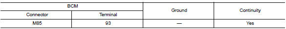
Is the inspection result normal? Yes >> inspection end.
No >> repair harness or connector.
Bcm (body control system) (without intelligent key system)
Bcm (body control system) (without intelligent key system) : diagnosis procedure
Regarding wiring diagram information, refer to bcs-111, "wiring diagram".
1.Check fuses and fusible link
Check that the following fuses and fusible link are not blown.

Is the fuse blown?
Yes >> replace the blown fuse or fusible link after repairing the affected circuit.
No >> go to 2.
2.Check power supply circuit
- Turn ignition switch off.
- Disconnect bcm connectors.
- Check voltage between bcm connector and ground.

Is the inspection result normal? YES >> GO TO 3.
NO >> Repair harness or connector.
3.Check ground circuit
Check continuity between bcm connector and ground.

Is the inspection result normal? Yes >> inspection end.
No >> repair harness or connector.

 Meter buzzer circuit
Description
The buzzer for warning chime system is installed in the combination
meter.
The combination meter sounds the alarm buzzer based on the signals
transmitted from various units.
...
Other materials:
Component parts
STARTING SYSTEM (WITH INTELLIGENT KEY)
Component Parts Location
Starter motor
Transmission range switch (CVT Models)
IPDM E/R (view with air inlet duct
removed)
Clutch interlock switch (M/T Models)
ECM
BCM (view under instrument panel,
left side of vehicle)
Component Descri ...
Main line between ipdm-e and dlc
circuit
Diagnosis procedure
1.Check connector
Turn the ignition switch off.
Disconnect the battery cable from the negative terminal.
Check the following terminals and connectors for damage, bend and loose
connection (connector side
and harness side).
Harness connector E4
Harness connec ...
Push-Button Ignition Switch (if so equipped)
WARNINGDo not operate the push-button ignition
switch while driving the vehicle except in
an emergency. (The engine will stop when
the ignition switch is pushed 3 consecutive
times in quick succession or the ignition
switch is pushed and held for more
than 2 seconds.) If ...
