Nissan Sentra Service Manual: Rear seat
Exploded View

- Rear seatback assembly (RH)
- Seatback striker
- Seatback latch release knob
- Seatback latch assembly
- Seatback silencer (RH)
- Rear seatback frame (RH)
- Seatback latch release knob finisher
- Rear seat bolster trim (RH)
- Rear seat bolster pad (RH)
- Rear seat bolster (RH)
- Seatback trim (RH)
- Seatback pad (RH)
- Seatback hinge bracket (RH)
- LATCH bracket (RH)
- Seat cushion assembly
- Seat cushion hook
- Seat cushion pad
- Seat cushion trim
- Seatback hinge bracket (center)
- LATCH bracket (LH)
- Seatback hinge bracket (LH)
- Armrest pivot bolt finisher
- Armrest pivot bolt
- Armrest hinge bracket
- Armrest bushing (LH)
- Armrest bushing (RH)
- Armrest assembly
- Armrest hinge finisher
- Seatback pad (LH)
- Seatback trim (LH)
- Rear seat bolster pad (LH)
- Rear seat bolster trim (LH)
- Rear seat bolster (LH)
- Rear seatback frame (LH)
- Seatback silencer (LH)
- Rear seatback assembly (LH)
Removal and Installation - Seat Cushion Assembly
REMOVAL
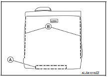
- Lift up the seat cushion assembly close to the front edge (B) to release it from the seat cushion hooks (A) (one for each side) and remove the seat cushion assembly.
 Front
Front

INSTALLATION
Installation is in the reverse order of removal.
Removal and Installation - 60:40 Split Seatback
REMOVAL
- Place the rear seatback assembly in the folded down position.
- Release the hook fasteners (A) in the lower corners of the rear seatback assembly.
- Remove the rear seatback assembly bolts (B) from the seatback hinge brackets (1), then remove the rear seatback assembly.

INSTALLATION
Installation is in the reverse order of removal.
- Tighten the rear seatback assembly bolts to specification. Refer to SE-22, "Exploded View".
Removal and Installation - Armrest Assembly
REMOVAL
- Place the rear seatback assembly (LH) in the folded down position.
- Release the J-hook retainer (A) and unzip the seatback trim zippers (B).
- Remove two nuts (A) and the armrest assembly.

INSTALLATION
Installation is in the reverse order of removal.
Removal and Installation - Rear Seat Bolster
REMOVAL
- Remove the seat cushion assembly. Refer to SE-23, "Removal and Installation - Seat Cushion Assembly".
- Remove the seat belt from the seat belt guide.
- Remove the bolt at bottom of rear seat bolster.
- Lift the rear seat bolster to remove.
INSTALLATION
Installation is in the reverse order of removal.
- Tighten rear seat bolster bolt to specification. Refer to SE-22, "Exploded View".
Removal and Installation - Seat Cushion Hook
REMOVAL
- Remove the seat cushion assembly. Refer to SE-23, "Removal and Installation - Seat Cushion Assembly".
- Release the seat cushion hook pawls as shown and remove.
CAUTION:
Before removing/installing the seat cushion hook, check its orientation (front/rear).

INSTALLATION
Installation is in the reverse order of removal.
Removal and Installation - Seatback Striker
REMOVAL
- Place the rear seatback assemblies (LH/RH) in the folded down position.
- Remove the top three clips of the rear seatback finisher and position aside to access the seatback striker bolts. Refer to INT-32, "Exploded View".
- Remove bolts (A) and the seatback strikers (1).
NOTE:
Rear seatback finisher removed for clarity.

INSTALLATION
Installation is in the reverse order of removal.
- Tighten the seatback striker bolts to specification. Refer to SE-22, "Exploded View".
Removal and Installation - Seatback Hinge Bracket
REMOVAL
- Remove the rear seatback assemblies (LH/RH). Refer to SE-23, "Removal and Installation - 60:40 Split Seatback".
- Remove the seat cushion assembly. Refer to SE-23, "Removal and Installation - Seat Cushion Assembly".
- Remove rear seatback hinge bracket bolts (A) and remove.
- Seatback hinge bracket (RH)
- Seatback hinge bracket (center)
- Seatback hinge bracket (LH)

INSTALLATION
Installation is in the reverse order of removal.
- Tighten the seatback hinge brackets to specification. Refer to SE-22, "Exploded View".
 Front seat
Driver side
DRIVER SIDE : Exploded View
Driver side
Headrest
Headrest holder (locked)
Headrest holder (free)
Seatback silencer
Seatback trim
Seatback pad
Seat belt buckle
Seat ...

Other materials:
Fuel level sensor signal circuit
Description
The fuel level sensor unit and fuel pump detects the approximate fuel level
in the fuel tank and transmits the
fuel level signal to the combination meter.
Component function check
1.Combination meter input signal
Select meter/m&a on consult.
Using FUEL METER of DATA MONI ...
VDC/TCS/ABS
Symptom Table
If ABS warning lamp and SLIP indicator lamp turn ON, perform
self-diagnosis.
NOTE:
1: The ABS does not operate when the speed is 10 km/h
(6 MPH) or less.
2: Under the following conditions, ABS is activated
and vibration is felt when brake pedal is lightly depr ...
Compression pressure
Inspection
Warm up the engine to full operating temperature.
Release fuel pressure. Refer to EC-143, "Work Procedure".
Remove ignition coil and spark plug from each cylinder. Refer to EM-46,
"Exploded View".
Connect engine tachometer (not required in use of CONSULT). ...
