Nissan Sentra Service Manual: Clutch fluid
Inspection
FLUID LEAKAGE
- Check clutch line for cracks, deterioration or other damage. Replace any damaged parts.
- Check for fluid leakage by fully depressing clutch pedal while engine is running.
CAUTION:
If leakage occurs around connections, reinstall the lines or replace damaged parts, if necessary.
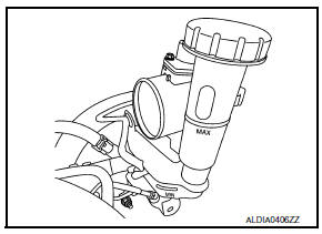
FLUID LEVEL
- Check that the fluid level in the reservoir tank is within the specified range, between the MAX and MIN lines as shown.
- Visually check for any clutch fluid leaks around the reservoir tank
- Check the clutch system for any leaks if the fluid level is extremely low (lower than MIN).
Draining
CAUTION:
Do not spill clutch fluid onto painted surfaces. If fluid spills, wipe up immediately and wash the affected area with water.
- Connect a transparent vinyl hose to air bleeder of bleeding connector (1).

- Press the lock pin (1) into the bleeding connector (2), and maintain the position.

- Slide bleeding connector (1) in the direction of the arrow ( ) as shown.
- Clutch housing
Dimension (A) : 10 mm (0.39 in)

- Depress clutch pedal to gradually discharge clutch fluid.
CAUTION:
Clutch tube is under hydraulic pressure; do not allow the clutch tube to disconnect from the bleeding connector.
Refilling
CAUTION:
Do not spill clutch fluid onto painted surfaces. If fluid spills, wipe up immediately and wash the affected area with water.
- Check that there is no foreign material in reservoir tank, and then fill with new clutch fluid.
CAUTION:
Do not reuse drained clutch fluid.
- Connect a transparent vinyl hose to air bleeder of bleeding connector (1).

- Press the lock pin (1) into the bleeding connector (2), and maintain the position.

- Slide bleeding connector (1) for the specified distance (A) in the
direction of the arrow (
 ) as
) as
shown.
(2) : Clutch housing

- Slowly depress clutch pedal to the full stroke position, and then release the pedal.
CAUTION:
Clutch tube is under hydraulic pressure; do not allow the clutch tube to disconnect from the clutch housing.
- Repeat step 5 at intervals of 2 or 3 seconds until new clutch fluid is discharged.
CAUTION:
Monitor clutch fluid level in reservoir tank so as not to empty the tank.
- Return clutch tube and lock pin in their original positions while clutch pedal is depressed.
- Perform the air bleeding. Refer to CL-9, "Air Bleeding".
Air Bleeding
CAUTION:
- Monitor clutch fluid level in reservoir tank so as not to empty the tank.
- Do not spill clutch fluid onto painted surfaces. If fluid spills, wipe up immediately and wash the affected area with water.
- Fill reservoir tank with new clutch fluid.
CAUTION:
Do not reuse drained clutch fluid.
- Connect a transparent vinyl hose to air bleeder of bleeding connector (1).
- Depress and release the clutch pedal slowly and fully 15 times at an interval of 2 to 3 seconds and release the clutch pedal.

- Press the lock pin (1) into the bleeding connector (2), and maintain the position.

- Slide bleeding connector (1) in the direction of the arrow ( ) as shown and immediately depress the clutch pedal and hold it, to bleed the air from the system.
(2) : Clutch housing
Dimension (A) : 10 mm (0.39 in)

Dimension (A) : 10 mm (0.39 in)
CAUTION:
Clutch tube is under hydraulic pressure; do not allow the clutch tube to disconnect from the clutch housing.
- Return clutch tube and lock pin in their original positions.
- Release clutch pedal and wait for 5 seconds
- Repeat steps 3 to 7 until no bubbles are observed in the clutch fluid.
- Check that the fluid level in the reservoir tank is within the specified range after air bleeding. Refer to CL- 7, "Inspection".
 Clutch pedal
Inspection and Adjustment
INSPECTION
The Height of Clutch Pedal
Pull back the floor trim and remove front floor spacer (LH) for access
to floor panel.
Check that the clutch pedal height (H1 ...

Other materials:
Basic inspection
Diagnosis and repair work flow
Work flow
Overall sequence
Detailed flow
1.Get information for symptom
Get detailed information from the customer about the symptom (the
condition and the environment when
the incident/malfunction occurs).
Check operation condition of the component o ...
P0444, P0445 EVAP Canister purge volume control solenoid valve
DTC Logic
DTC DETECTION LOGIC
DTC No.
CONSULT screen terms
(Trouble diagnosis content)
DTC detecting condition
Possible cause
P0444
PURG VOLUME CONT/V
(Evaporative emission system
purge control valve circuit open)
An excessively low voltage signal is sent to ...
A/c auto amp. Connection recognition signal circuit
Description
A/c auto amp. Transmits the a/c auto amp. Connection recognition signal to
the combination meter
Diagnosis procedure (with manual a/c)
Regarding wiring diagram information, refer to mwi-28, "wiring diagram".
1.Check a/c auto amp. Connection recognition signal
Turn ig ...
