Nissan Sentra Service Manual: Fuel pump
Component Function Check
1.CHECK FUEL PUMP FUNCTION
- Turn ignition switch ON.
- Pinch fuel feed hose
 with
with
two fingers.

Fuel pressure pulsation should be felt on the fuel feed hose for 1 second after ignition switch is turned ON.
Is the inspection result normal? YES >> INSPECTION END
NO >> Proceed to EC-453, "Diagnosis Procedure".
Diagnosis Procedure
1.CHECK FUEL PUMP POWER SUPPLY CIRCUIT-1
- Turn ignition switch OFF.
- Disconnect ECM harness connector.
- Turn ignition switch ON.
- Check the voltage between ECM harness connector and ground.

Is the inspection result normal? YES >> GO TO 3.
NO >> GO TO 2.
2.CHECK FUEL PUMP POWER SUPPLY CIRCUIT-2
- Turn ignition switch OFF.
- Disconnect IPDM E/R harness connector.
- Check the continuity between IPDM E/R harness connector and ECM harness connector.

- Also check harness for short to ground and short to power.
Is the inspection result normal? YES >> GO TO 8.
NO >> Repair or replace error-detected parts.
3.CHECK FUEL PUMP POWER SUPPLY CIRCUIT-3
- Turn ignition switch OFF.
- Reconnect all harness connectors disconnected.
- Disconnect fuel pump harness connector.
- Turn ignition switch ON.
- Check the voltage between fuel pump harness connector and ground.
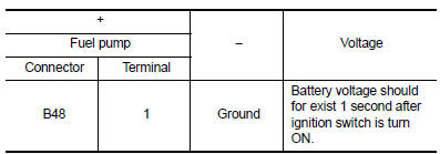
Is the inspection result normal? YES >> GO TO 6.
NO >> GO TO 4.
4.CHECK FUSE
- Turn ignition switch OFF.
- Disconnect 15A fuse (No. 50) from IPDM E/R.
- Check 15A fuse.
Is the inspection result normal? YES >> GO TO 5.
NO >> Replace 15A fuse.
5.CHECK FUEL PUMP POWER SUPPLY CIRCUIT-4
- Turn ignition switch OFF.
- Disconnect IPDM E/R harness connector
- Check the continuity between IPDM E/R harness connector and fuel pump harness connector.

- Also check harness for short to ground and short to power.
Is the inspection result normal? YES >> GO TO 6.
NO >> Repair or replace error-detected parts.
6.CHECK FUEL PUMP GROUND CIRCUIT
- Turn ignition switch OFF.
- Check the continuity between fuel pump harness connector and ground.

- Also check harness for short to power.
Is the inspection result normal? YES >> GO TO 7.
NO >> Repair or replace error-detected parts.
7.CHECK FUEL PUMP
Check fuel pump. Refer to EC-455, "Component Inspection (Fuel Pump)".
Is the inspection result normal? YES >> GO TO 8.
NO >> Replace fuel filter and fuel pump. Refer to FL-6, "Exploded View".
8.CHECK INTERMITTENT INCIDENT
Check intermittent incident. Refer to GI-39, "Intermittent Incident".
Is the inspection result normal? YES >> Replace IPDM E/R. Refer to PCS-30, "Removal and Installation" (With intelligent key) or PCS-58, "Removal and Installation" (Without intelligent key).
NO >> Repair or replace error-detected parts.
Component Inspection (Fuel Pump)
1.CHECK FUEL PUMP
- Turn ignition switch OFF
- Disconnect fuel level sensor unit and fuel pump harness connector.
- Check resistance between fuel pump terminals as follows.

Is the inspection result normal? YES >> INSPECTION END
NO >> Replace fuel filter and fuel pump. Refer to FL-6, "Removal and Installation".
 Fuel injector
Component Function Check
1.INSPECTION START
Turn ignition switch to START.
Is any cylinder ignited?
YES >> GO TO 2.
NO >> Proceed to EC-450, "Diagnosis Procedure".
2.CH ...
 Ignition signal
Component Function Check
1.INSPECTION START
Turn ignition switch OFF.
Start engine.
Does the engine start?
YES >> GO TO 2.
NO >> Proceed to EC-456, "Diagnosis Procedure& ...
Other materials:
Bluetooth® Hands-Free Phone System without Navigation System (Type A) (if so
equipped)
WARNING
Use a phone after stopping your vehicle
in a safe location. If you have to use a
phone while driving, exercise extreme
caution at all times so full attention may
be given to vehicle operation.
If you are unable to devote full attention
to vehicle operation ...
The door open warning continues displaying, or does not display
Description
The door ajar warning is displayed even though all of the doors are
closed.
The door ajar warning is not displayed even though a door is ajar.
Diagnosis procedure
1.Check bcm input signal
Check the bcm input signal. Refer to dlk-102, "component function check"
( ...
Diagnosis system (ipdm e/r) (without intelligent key system)
Diagnosis Description
AUTO ACTIVE TEST
Description
In auto active test, the IPDM E/R sends a drive signal to the following
systems to check their operation.
Front wiper (LO, HI)
Parking lamp
License plate lamp
Tail lamp
Front fog lamp (if equipped)
Headlamp (LO, HI)
A/C compress ...
