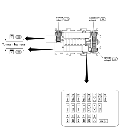
Nissan Sentra Service Manual: Fuse block - junction box (J/B)
Terminal arrangement

 Standardized relay
Description
Normal open, normal closed and mixed type relays
Relays can mainly be divided into three types: normal open, normal closed and
mixed type relays.
Type of standardized relays
...
 Fuse, fusible link and relay box
Terminal arrangement
Fuse and fusible link box
...
Other materials:
Checking engine oil level
Park the vehicle on a level surface and apply
the parking brake.
Start the engine and let it idle until it reaches
operating temperature.
Turn off the engine. Wait more than
10 minutes for the oil to drain back into
the oil pan.
Remove the dipstick and wipe it clean. Reinsert
...
Precaution for Brake Control System
Always perform a pre-driving check to drive the vehicle.
Always check speed and safety while driving the vehicle.
To operate CONSULT while driving, more than one person is
required to be in the vehicle to avoid interference
to driving and ensure safety.
Slight vibrations ar ...
Preparation
Special Service Tools
The actual shape of the tools may differ from those illustrated here.
Commercial Service Tools
...
