Nissan Sentra Service Manual: Optical sensor
Description
The optical sensor measures ambient light and transmits the optical sensor signal to the bcm.
Component function check
1.Check optical sensor signal by consult
 Consult
- Turn the ignition switch ON.
- Select opti sen of bcm (head lamp) data monitor item.
- Turn the lighting switch to AUTO.

*: Illuminates the optical sensor. The value may be less than the standard value if brightness is weak.
Is the inspection result normal? YES >> Optical sensor is normal.
NO >> Refer to EXL-103, "Diagnosis Procedure".
Diagnosis procedure
Regarding Wiring Diagram information, refer to EXL-53, "Wiring Diagram".
1.Check optical sensor power supply input
- Turn the ignition switch off
- Disconnect the optical sensor harness connector.
- Turn the ignition switch ON.
- Turn the lighting switch to auto.
- Check the voltage between the optical sensor harness connector and ground.
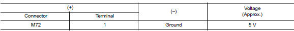
Is the inspection result normal? Yes >> go to 2.
No >> go to 3.
2.Check optical sensor ground circuit
- Turn the ignition switch off.
- Check continuity between the optical sensor harness connector and ground.

Is the inspection result normal? YES >> GO TO 4.
NO >> GO TO 5.
3.Check optical sensor power supply for open circuit
- Turn the ignition switch off.
- Disconnect the bcm harness connector.
- Check continuity between optical sensor harness connector and bcm harness connector.

- Check continuity between optical sensor harness connector and ground.

Is the inspection result normal? Yes >> replace bcm. Refer to bcs-73, "removal and installation".
No >> repair or replace the harness or connectors.
4.Check optical sensor signal open circuit
- Disconnect optical sensor connector and bcm connector.
- Check continuity between optical sensor harness connector and bcm harness connector.

- Check continuity between optical sensor harness connector and ground.

Is the inspection result normal? Yes >> replace the optical sensor. Refer to exl-130, "removal and installation".
No >> repair or replace harness or connectors.
5.Check optical sensor ground for open circuit
- Disconnect the bcm harness connector.
- Check continuity between optical sensor harness connector and bcm harness connector.

Is the inspection result normal? YES >> Replace BCM. Refer to BCS-73, "Removal and Installation".
NO >> Repair or replace harness or connector.
 Turn signal lamp circuit
Description
The bcm monitors inputs from the combination switch to determine when to
activate the turn signals. The
bcm outputs voltage direction to the left and right turn signals during turn
...
 Hazard switch
Component function check
1.Check hazard switch signal by consult
Consult data monitor
Turn ignition switch ON.
Select hazard sw of bcm (flasher) data monitor item.
While operating the hazar ...
Other materials:
P1226 TP Sensor
DTC Logic
DTC DETECTION LOGIC
DTC No.
CONSULT screen terms
(Trouble diagnosis content)
DTC detecting condition
Possible cause
P1226
CTP LEARNING-B1
(CTP LEARNING-B1)
Closed throttle position learning is not performed
successfully, repeatedly.
Electric thr ...
Front wiper motor ground circuit
Diagnosis procedure
Regarding Wiring Diagram information, refer to WW-24, "Wiring Diagram - With
Intelligent Key" or WW-29,
"Wiring Diagram - Without Intelligent Key".
1.Check front wiper motor (gnd) open circuit
Turn the ignition switch OFF.
Disconnect front wiper mot ...
ECU diagnosis information
A/C AUTO AMP
Reference Value
TERMINAL LAYOUT
PHYSICAL VALUES
*:With manual A/C
ECM, IPDM E/R, BCM
List of ECU Reference
...
