Nissan Sentra Service Manual: Parking brake shoe
Removal and Installation - Drum Brake
If equipped with drum brakes, refer to BR-42, "Removal and Installation".
Exploded View - Disc Brake

-
Anti-rattle pin
-
Back plate
-
Toggle lever
-
Parking brake shoe
-
Brake strut
-
Return spring
-
Spring
-
Adjuster
 Apply PBC (Poly
Butyl Cuprysil)
grease or silicone based grease
Removal and Installation - Disc Brake
REMOVAL
WARNING:
Clean dust on the parking brake shoes with a vacuum dust collector to minimize the hazard of air borne particles or other materials.
-
Remove rear wheels and tires using power tool. Refer to WT-47, "Adjustment".
-
Remove disc rotor. Refer to RAX-7, "Removal and Installation - Disc brake".
CAUTION:
Parking brake must be completely released before removing rotor.
-
Remove return springs (1) from the top of the parking brake shoes.

-
Remove the return spring (1) from the lower side of the parking brake shoes.

-
Remove springs (1) from the parking brake shoes.
CAUTION:
Do not drop the removed parts.
-
Remove parking brake shoes, adjuster, brake strut and toggle lever.
CAUTION:
-
The front parking brake shoes are made of different materials than the rear parking brake shoes. Install the parking brake shoes in the proper location.
-
Do not drop the removed parts.
-
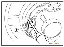
Press the rear cable spring (1) against spring tension to remove rear cable (3) from the clamp (A) of toggle lever (2).
CAUTION:
Do not bend rear cable.
-
Remove back plate (if necessary). Refer to RAX-7, "Removal and Installation - Disc brake".

INSTALLATION
Installation is in the reverse order of removal.
-
Apply PBC (Poly Butyl Cuprysil) grease or silicone-based grease to the back plate and brake shoe.
CAUTION:
The front parking brake shoes are made of different materials than the rear parking brake shoes.
Install the parking brake shoes in the proper location.
-
Assemble adjusters so that threaded part is expanded when rotating it in the direction shown by arrow.
(A) : For (RH) brake
(B) : For (LH) brake
 : Front
 : Adjuster expands
-
Shorten adjuster by rotating it.
-
When disassembling apply PBC (Poly Butyl Cuprysil) grease or silicone- based grease to threads.

-
Check that the component parts of the parking brake shoe are properly installed.
-
Check parking brake shoe sliding surface and drum inner surface for grease. Make sure that grease does not adhere to the friction mating surfaces on the parking brake shoes and disc rotor.

Inspection and Adjustment
INSPECTION AFTER REMOVAL
Lining Thickness Inspection
-
Check thickness (A) of lining.
Wear limit thickness : Refer to PB-13, "Parking Drum Brake".

Drum Inner Diameter Inspection
-
Check inner diameter (B) of drum using suitable tool.
Wear limit of inner diameter : Refer to PB-13, "Parking Drum Brake".

Other Inspections
Check the following items, and replace the parts if necessary.
-
Lining for excessive wear, damage, and peeling.
-
Brake shoe sliding surface for excessive wear and damage
-
Anti-rattle pin for excessive wear, damage and rust.
-
Return spring and spring for settling, excessive wear, damage, and rust.
-
Adjuster for smoothness.
-
Toggle lever and brake strut for excessive wear, damage and rust.
-
Visually check inside of the drum for excessive wear, cracks, and damage.
ADJUSTMENT AFTER INSTALLATION
-
Adjust the parking brake lever stroke. Refer to PB-4, "Inspection and Adjustment".
-
Rotate the disc rotor to check that there is no drag. Install the plug. If any drag is found, follow the procedure described below.
-
Adjust parking brake stroke again.
-
Check rear disc brake.
-
Adjust the parking brake shoe. Refer to PB-6, "Adjustment - Disc Brake".
 Parking brake control
Exploded View
Parking brake lever assembly
Adjusting nut
Parking brake switch
Front parking brake cable
Rear parking brake cable (LH)
Rear parking brake cable (RH) ...
 Service data and specifications (SDS)
Parking Drum Brake
Parking Brake Control
...
Other materials:
Head restraints/Headrests
WARNINGHead restraints/headrests supplement
the other vehicle safety systems. They may
provide additional protection against injury
in certain rear end collisions. Adjustable
head restraints/headrests must be
adjusted properly, as specified in this section.
Check the adjus ...
Passenger compartment
CAUTION
Never use a fuse of a higher or lower
amperage rating than specified on the
fuse box cover. This could damage the
electrical system or cause a fire.
If any electrical equipment does not operate,
check for an open fuse.
NOTE:
The fuse box is located on the driver’s side
of the ...
Dtc/circuit diagnosis
Sport mode switch
Component function check
1. Check sport mode switch operation
Turn ignition switch on.
Check sport mode indicator lamp turns on/off on combination meter when
turn sport mode switch
on/off.
Is the inspection result normal?
Yes >> inspection end.
No >> ...
