Nissan Sentra Service Manual: Power supply and ground circuit
Combination meter
COMBINATION METER : Diagnosis Procedure
Regarding Wiring Diagram information, refer to MWI-28, "Wiring Diagram".
1.Check fuses
Check that the following fuses are not blown.

Is the fuse blown? Yes >> replace the blown fuse after repairing the affected circuit.
No >> go to 2.
2.Power supply circuit check
Check voltage between combination meter harness connector m24 terminals 15, 27, 28 and ground

Is the inspection result normal? YES >> GO TO 3.
NO >> Repair or replace harness or connector.
3.Check ground circuit
Check continuity between combination meter harness connector m24 terminals 21, 22, 23 and ground.

Is the inspection result normal? Yes >> inspection end.
No >> repair or replace harness or connector.
Bcm (body control system) (with intelligent key system)
Bcm (body control system) (with intelligent key system) : diagnosis procedure
Regarding wiring diagram information, refer to bcs-51, "wiring diagram".
1.Check fuses and fusible link
Check that the following fuses and fusible link are not blown.

Is the fuse blown? Yes >> replace the blown fuse or fusible link after repairing the affected circuit.
No >> go to 2.
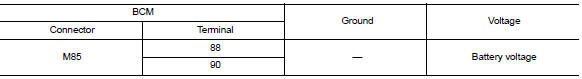
2.Check power supply circuit
- Disconnect bcm connector m85.
- Check voltage between BCM connector M85 and ground.
Is the inspection result normal? Yes >> go to 3.
No >> repair harness or connector.
3.Check ground circuit
Check continuity between bcm connector m85 and ground.

Is the inspection result normal? Yes >> inspection end.
No >> repair harness or connector.
Bcm (body control system) (without intelligent key system)
Bcm (body control system) (without intelligent key system) : diagnosis procedure
Regarding Wiring Diagram information, refer to BCS-111, "Wiring Diagram".
1.Check fuses and fusible link
Check that the following fuses and fusible link are not blown.

Is the fuse blown? Yes >> replace the blown fuse or fusible link after repairing the affected circuit.
No >> go to 2.
2.Check power supply circuit
- Turn ignition switch off.
- Disconnect bcm connectors.
- Check voltage between bcm connector and ground.

Is the inspection result normal? YES >> GO TO 3.
NO >> Repair harness or connector.
3.Check ground circuit
Check continuity between BCM connector and ground.

Is the inspection result normal? Yes >> inspection end.
No >> repair harness or connector.
 B2268 water temp
Description
The engine coolant temperature signal is transmitted from ecm to the
combination meter via can communication.
Dtc logic
Dtc detection logic
Dtc
Consult
Detection condit ...
 Steering switch (meter control switch) signal circuit
Diagnosis Procedure
Regarding wiring diagram information, refer to mwi-28, "wiring diagram".
1.Check combination meter input signal
Turn ignition switch on.
Measure voltage between ...
Other materials:
Multiport fuel injection system
MULTIPORT FUEL INJECTION SYSTEM : System
Description
SYSTEM DIAGRAM
*1: ECM determines the start signal status by the signals of engine speed and
battery voltage.
*2: M/T models
*3: CVT models
*4: This sensor is not used to control the engine system under normal
conditions.
SYSTEM DES ...
Engine compartment check locations
MRA8DE engine
Engine oil filler cap
Brake and clutch (if so equipped) fluid
reservoir
Air cleaner
Battery
Fuse/fusible link box
Engine coolant reservoir
Radiator cap
Engine oil dipstick
Drive belt location
Windshield-washer fluid reservoir
...
Road wheel tire assembly
Exploded View
Removal and Installation
REMOVAL
Remove wheel nuts.
Remove wheel and tire.
INSTALLATION
Installation is in the reverse order of removal.
Adjustment
BALANCING WHEELS (ADHESIVE WEIGHT TYPE)
Preparation Before Adjustment
Remove inner and outer balance weights from the ...
