Nissan Sentra Service Manual: Removal and installation
A/C ASSEMBLY SWITCH
Removal and Installation
Removal
- Remove the cvt shift selector finisher (cvt: re0f11a). Refer to tm-253, "removal and installation".
- Remove the MT shift selector finisher (6MT: RS6F94R). Refer to TM-22, "Exploded View".
- Remove the front air control screws.
- Release the front air control metal clips using a suitable tool.
- Disconnect the harness connectors from the A/C assembly switch and remove.
Installation
Installation is in the reverse order of removal.
A/C AUTO AMP
Exploded View

- AV control unit bracket (LH)
- AV control unit bracket (RH)
- A/C auto amp.
- AV control unit
Removal and Installation
REMOVAL
- Remove the AV control unit. Refer to AV-406, "Removal and Installation".
- Remove the AV control unit bracket screws (A).

- Remove the A/C auto amp.
INSTALLATION
Installation is in the reverse order of removal.
INTAKE SENSOR
Removal and Installation
The intake sensor is serviced as an assembly with the heating and cooling unit assembly. Refer to HA-43, "HEATING AND COOLING UNIT ASSEMBLY : Removal and Installation".
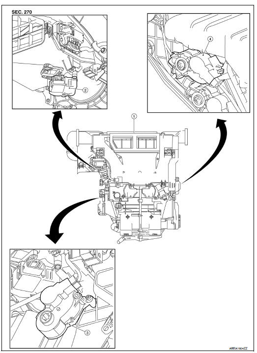
Refrigerant pressure sensor
Removal and Installation
REMOVAL
- Discharge the refrigerant. Refer to HA-23, "Recycle Refrigerant".
- Remove the core support upper. Refer to HA-39, "Exploded View".
- Disconnect the harness connector from the refrigerant pressure sensor.
- Remove the refrigerant pressure sensor (1).
CAUTION:
Cap or wrap the opening of the refrigerant pressure sensor with suitable material such as vinyl tape to avoid the entry of air.

Installation
Installation is in the reverse order of removal.
Caution:
- Do not reuse o-ring.
- Apply a/c oil to the o-ring of the refrigerant pressure sensor for installation.
- After charging refrigerant, check for leaks. Refer to ha-21, "leak test".
Door motor
Exploded View
- Heating and cooling unit assembly
- Intake door motor
- Mode door motor
- Air mix door motor
INTAKE DOOR MOTOR
INTAKE DOOR MOTOR : Removal and Installation
Removal
- Remove the heating and cooling unit assembly. Refer to ha-43, "heating and cooling unit assembly : removal and installation".
- Disconnect the harness connector from the intake door motor.
- Remove the intake door motor screws and the intake door motor.
Installation
Installation is in the reverse order of removal.
MODE DOOR MOTOR
MODE DOOR MOTOR : Removal and Installation
Removal
- Remove the front floor duct LH. Refer to HA-42, "Exploded View".
- Disconnect the harness connector from the mode door motor.
- Remove the mode door motor screws and the mode door motor.
Installation
Installation is in the reverse order of removal.
AIR MIX DOOR MOTOR
AIR MIX DOOR MOTOR : Removal and Installation
Removal
- Remove the glove box assembly. Refer to IP-22, "Removal and Installation".
- Disconnect the harness connector from the air mix door motor
- Remove the air mix door motor screws and the air mix door motor.
Installation
Installation is in the reverse order of removal.
BLOWER MOTOR RESISTOR
Removal and Installation
Removal
- Remove the instrument lower panel LH. Refer to IP-21, "Removal and Installation".
- Disconnect the harness connector from the blower motor resistor.
- Release the pawls using a suitable tool and remove the blower motor resistor.
Installation
Installation is in the reverse order of removal.
 Symptom diagnosis
HEATER AND AIR CONDITIONING SYSTEM
CONTROL SYMPTOMS
Symptom Table
INSUFFICIENT COOLING
Component Function Check
Symptom: insufficient cooling
Inspection flow
1. Confirm symptom by performin ...
 Body interior
...
Other materials:
Specifications
Engine
This spark ignition system complies with the Canadian standard ICES-002.
Wheels and tires
Dimensions and weights
...
Information voice commands
The following voice commands are available for
the information functions of the Navigation System:
Traffic
Fuel Prices
Stocks
Movie Listings
Current Weather
Weather Map
5 — day Forecast
6 — hour Forecast
For more information about these commands,
see the separate Navigatio ...
Vehicle information
Body exterior paint color
M = Metallic, S = Solid, 2S = Solid and Clear, 2P = 2-Coat Pearl, 3P = 3-Coat
Pearl, PM = Pearl Metallic, t = Primerless Diamond Clear
coat, Black is solvent based, all others are water based. ...
