Nissan Sentra Service Manual: Strg branch line circuit
Diagnosis procedure
1.Check connector
- Turn the ignition switch off.
- Disconnect the battery cable from the negative terminal.
- Check the terminals and connectors of the steering angle sensor for damage, bend and loose connection (unit side and connector side).
Is the inspection result normal? YES >> GO TO 2.
NO >> Repair the terminal and connector.
2.Check harness for open circuit
- Disconnect the connector of steering angle sensor.
- Check the resistance between the steering angle sensor harness connector terminals.
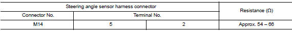
Is the measurement value within the specification? Yes >> go to 3.
No >> repair the steering angle sensor branch line.
3.Check power supply and ground circuit
Check the power supply and the ground circuit of the steering angle sensor. Refer to BRC-44, "Wiring Diagram".
Is the inspection result normal? YES (Present error)>>Replace the steering angle sensor. Refer to BRC-113, "Removal and Installation".
YES (Past error)>>Error was detected in the steering angle sensor branch line.
NO >> Repair the power supply and the ground circuit.
 M&A branch line circuit
Diagnosis procedure
1.Check connector
Turn the ignition switch off.
Disconnect the battery cable from the negative terminal.
Check the terminals and connectors of the combination meter for da ...
 Hvac branch line circuit
Diagnosis procedure
1.Check connector
Turn the ignition switch OFF.
Disconnect the battery cable from the negative terminal
Check the terminals and connectors of the a/c auto amp. For damage, ...
Other materials:
A-bag branch line circuit
Diagnosis procedure
Warning:
Always observe the following items for preventing accidental
activation.
Before servicing, turn ignition switch off, disconnect battery
negative terminal, and wait 3 minutes
or more. (To discharge backup capacitor.)
Never use unspecified tester or other me ...
Removal and installation
Bcm (body control module)
Removal and Installation
Note:
Before replacing bcm, perform “read configuration” to save or print
current vehicle specification. Refer
to bcs-116, "configuration (bcm) : description".
Removal
Disconnect the negative battery terminal. Refer to ...
Precaution for Supplemental Restraint System (SRS) "AIR BAG"
and "SEAT BELT PRE-TENSIONER"
The Supplemental Restraint System such as “AIR BAG” and “SEAT
BELT PRE-TENSIONER”, used along
with a front seat belt, helps to reduce the risk or severity of injury to the
driver and front passenger for certain
types of collision. Information necessary to service the system ...
