Nissan Sentra Service Manual: Can communication circuit
Diagnosis procedure
1.Connector inspection
- Turn the ignition switch OFF.
- Disconnect the battery cable from the negative terminal.
- Disconnect all the unit connectors on can communication system.
- Check terminals and connectors for damage, bend and loose connection.
Is the inspection result normal? Yes >> go to 2.
No >> repair the terminal and connector.
2.Check harness continuity (short circuit)
Check the continuity between the data link connector terminals.

Is the inspection result normal? Yes >> go to 3.
No >> check the harness and repair the root cause.
3.Check harness continuity (short circuit)
Check the continuity between the data link connector and the ground.

Is the inspection result normal? YES >> GO TO 4.
NO >> Check the harness and repair the root cause.
4.Check ecm and bcm termination circuit
- Remove the ecm and the bcm.
- Check the resistance between the ecm terminals.
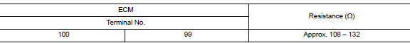
- Check the resistance between the bcm terminals.

Is the measurement value within the specification? YES >> GO TO 5.
NO >> Replace the ECM and/or the BCM.
5.Check symptom
Connect all the connectors. Check if the symptoms described in the –≤–Ç—ösymptom (results from interview with customer)–≤–Ç—ú are reproduced.
Inspection result
Reproduced>>go to 6.
Non-reproduced>>start the diagnosis again. Follow the trouble diagnosis procedure when past error is detected.
6.Check unit reproduction
Perform the reproduction test as per the following procedure for each unit.
- Turn the ignition switch off.
- Disconnect the battery cable from the negative terminal.
- Disconnect one of the unit connectors of can communication system.
Note:
Ecm and bcm have a termination circuit. Check other units first.
- Connect the battery cable to the negative terminal. Check if the symptoms described in the –≤–Ç—ösymptom (results from interview with customer)–≤–Ç—ú are reproduced.
Note:
Although unit-related error symptoms occur, do not confuse them with other symptoms.
Inspection result
Reproduced>>connect the connector. Check other units as per the above procedure.
Non-reproduced>>replace the unit whose connector was disconnected.
 BCM branch line circuit
Diagnosis procedure
1.Check connector
Turn the ignition switch off.
Disconnect the battery cable from the negative terminal.
Check the terminals and connectors of the bcm for damage, bend and ...
 Can system (type 5)
Dtc/circuit diagnosis ...
Other materials:
Seat belts
The seat belts can be cleaned by wiping them
with a sponge dampened in a mild soap solution.
Allow the belts to dry completely in the shade
before using them. See “Seat belt maintenance”
in the “Safety – Seats, seat belts and supplemental
restraint system” section of this manual.
...
Power supply and ground circuit
Av control unit
Av control unit : diagnosis procedure
Regarding wiring diagram information, refer to av-331, "wiring diagram".
1.Check fuse
Check that the following fuses are not blown.
Are the fuses blown?
Yes >> replace the blown fuse after repairing the affected circuit. ...
Precaution
Precaution for Supplemental Restraint System (SRS) "AIR BAG" and "SEAT BELT
PRE-TENSIONER"
The supplemental restraint system such as –≤–Ç—öair bag–≤–Ç—ú and –≤–Ç—öseat belt pre-tensioner–≤–Ç—ú,
used along
with a front seat belt, helps to reduce the risk or severity of injur ...
