Nissan Sentra Service Manual: Diagnosis system (combination meter)
Description
COMBINATION METER SELF-DIAGNOSIS MODE
The information display, speedometer and tachometer can be checked in self-diagnosis mode.
STARTING COMBINATION METER SELF-DIAGNOSIS MODE
NOTE:
- Check combination meter power supply and ground circuits if self-diagnosis mode does not start. Refer to MWI-52, "COMBINATION METER : Diagnosis Procedure". Replace combination meter if power supply and ground circuits are found to be normal and self-diagnosis mode does not start. Refer to MWI-77, "Removal and Installation".
- Combination meter self-diagnosis mode will function with the ignition switch in ON. Combination meter selfdiagnosis mode will exit upon turning the ignition switch to OFF.
How to Initiate Self-Diagnosis Mode
- Turn ignition switch OFF.
- While pressing the steering switch 1 , turn ignition switch ON.
- If the diagnosis function is activated with “trip A” displayed, the mileage on “trip A” is reset to “0000.0”. (The same way for “trip B”.)

- Make sure that the trip meter displays “0000.0”.
- Press the steering switch 1 at least 3 times. (Within 7 seconds after the ignition switch is turned ON.)
- The combination meter is turned to self-diagnosis mode.
- Speedometer, tachometer, engine coolant temperature gauge, fuel gauge, and return to zero, simultaneously.
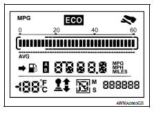
- All segments of the information display are displayed.
NOTE:
- Check the following items when the self-diagnosis mode of the
combination meter does not start.
Replace combination meter if the following items are normal.
- Combination meter power supply and ground circuit.
- Steering switch signal circuit and steering switch.
- If any of the dots are not displayed, replace combination meter.
- Each meter activates by pressing the steering switch .

NOTE:
- If any of the meters or gauges is not activated, replace combination meter.
- The figure is reference.
Consult function (meter/m&a)
APPLICATION ITEMS
CONSULT can perform the following diagnosis modes via CAN communication and the combination meter.

SELF DIAG RESULT
Refer to MWI-26, "DTC Index".
DATA MONITOR
Display Item List


NOTE:
Some items are not available according to vehicle specification.
WARNING HISTORY
- Stores histories when warning/indicator lamp is turned on.
- “WARNING HISTORY” indicates the “TIME” when the warning/ indicator lamp is turned on.
- The “TIME” above is:
- 0: The condition that the warning/indicator lamp has been turned on 1 or more times after starting the engine and waiting for 30 seconds.
- 1 - 39: The number of times the engine was restarted after the 0 condition.
- NO WARNING HISTORY: Stores NO (0) turning on history of warning/indicator lamp.
NOTE:
- WARNING HISTORY is not stored for approximately 30 seconds after the engine starts.
- Brake warning lamp does not store any history when the parking brake is applied or the brake fluid level gets low.
WORK SUPPORT
| Work support item | Description |
| Turn signal buzzer diagnosis | A possible malfunction can be narrowed down by following displayed instructions. |
| Outside air temperature diagnosis | |
| Fuel meter diagnosis (Analog pointer) | |
| Warning/Indicator lamp diagnosis |
 System
Meter system
Meter system : system diagram
Meter system : system description
COMBINATION METER
The combination meter receives signals from switches, sensors and modules to
control the foll ...

Other materials:
Air fresheners
Most air fresheners use a solvent that could affect
the vehicle interior. If you use an air freshener,
take the following precautions:
Hanging-type air fresheners can cause permanent
discoloration when they contact vehicle
interior surfaces. Place the air freshener
in a location that all ...
Eps branch line circuit
Diagnosis procedure
1.Check connector
Turn the ignition switch OFF.
Disconnect the battery cable from the negative terminal.
Check the terminals and connectors of the eps control unit for damage,
bend and loose connection (unit
side and connector side).
Is the inspection result norm ...
Diagnosis system (combination meter)
Consult function (meter/m&a)
Application items
Consult can perform the following diagnosis modes via can communication and
the combination meter.
Self diag result
Refer to mwi-26, "dtc index".
Data monitor
Display item list
Note:
Some items are not available accor ...
