Nissan Sentra Service Manual: Encoder
Driver side
DRIVER SIDE : Description
Detects condition of the front power window motor lh operation and transmits to main power window and door lock/unlock switch as pulse signal.
DRIVER SIDE : Component Function Check
1. Check encoder operation
Check front door glass lh perform auto open/close operation normally with main power window and door lock/unlock switch.
Is the inspection result normal? Yes >> encoder operation is ok.
No >> refer to pwc-50, "driver side : diagnosis procedure".
DRIVER SIDE : Diagnosis Procedure
Regarding wiring diagram information, refer to pwc-18, "wiring diagram".
Encoder circuit check
1. Check encoder operation
- Connect front power window motor lh.
- Turn ignition switch ON.
- Check signal between main power window and door lock/unlock switch connector d5 and ground with oscilloscope.

Is the inspection result normal? YES >> Check intermittent incident. Refer to GI-39, "Intermittent Incident".
NO >> GO TO 2.
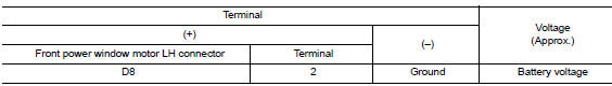
2. Check front power window motor lh power supply
- Turn ignition switch on.
- Check voltage between front power window motor lh connector d8 and ground.
Is the inspection result normal? YES >> GO TO 4.
NO >> GO TO 3.
3. Check harness continuity 1
- Turn ignition switch OFF.
- Disconnect main power window and door lock/unlock switch and front power window motor lh.
- Check continuity between main power window and door lock/unlock switch connector D5 and front power window motor connector D8.

- Check continuity between main power window and door lock/unlock switch connector d5 and ground.

Is the inspection result normal? YES >> Replace main power window and door lock/unlock switch. Refer to PWC-70, "Removal and Installation".
After that, refer to PWC-29, "Work Procedure".
NO >> Repair or replace harness or connectors.
4. Check ground circuit
- Turn ignition switch off.
- Disconnect front power window motor LH.
- Check continuity between front power window motor lh connector d8 and ground.

Is the inspection result normal? Yes >> go to 6.
No >> go to 5.
5. Check harness continuity 2
- Disconnect main power window and door lock/unlock switch.
- Check continuity between main power window and door lock/unlock switch connector d5 and front power window motor lh connector d8.

Is the inspection result normal? YES >> Check main power window and door lock/unlock switch. Refer to PWC-36, "POWER WINDOW MAIN SWITCH : Component Inspection".
NO >> Repair or replace the harness or connectors.
6. Check harness continuity 3
- Disconnect main power window and door lock/unlock switch.
- Check continuity between main power window d5 and door lock/unlock switch connector and front power window motor lh connector d8.

- Check continuity between main power window and door lock/unlock switch connector d5 and ground.

Is the inspection result normal? Yes >> replace front power window motor lh. Refer to gw-16, "removal and installation". After that, refer to pwc-29, "work procedure".
No >> repair or replace harness or connectors.
DRIVER SIDE : Special Repair Requirement
1. Perform initialization procedure
Perform initialization procedure.
Refer to pwc-29, "work procedure".
Is the inspection result normal? Yes >> inspection end.
No >> check intermittent incident. Refer to gi-39, "intermittent incident".
 Power window motor
DRIVER SIDE
DRIVER SIDE : Description
Door glass moves up/down by receiving the signal from main power window and
door lock/unlock switch
DRIVER SIDE : Component Function Check
1. Check front po ...
 Door switch
With intelligent key
WITH INTELLIGENT KEY : Component Function Check
1.Check function
Select DOOR LOCK of BCM using CONSULT.
Select DOOR SW-DR, DOOR SW-AS, DOOR SW-RL and DOOR SW-RR in DATA M ...
Other materials:
On board diagnosis function
ON BOARD DIAGNOSIS ITEM
The on board diagnostic system has the following functions.
Diagnostic test mode
Function
Bulb check
MIL can be checked.
SRT status
ECM can read if SRT codes are set.
Malfunction warning
If ECM detects a malfunction, it illumina ...
Battery current sensor
Exploded view
Battery current sensor
Current sensor harness connector
Removal and installation
Removal
Loosen the battery terminal nut and disconnect battery negative
terminal. Refer to PG-50, "Exploded
View".
Disconnect the harness connector from current sensor.
...
The braking distance is long
Diagnosis Procedure
CAUTION:
The stopping distance on slippery road surfaces might be
longer with the ABS operating than when
the ABS is not operating.
1.CHECK ABS FUNCTION
Turn ignition switch OFF.
Disconnect ABS actuator and electric unit (control unit)
connector to deactivate ...
