Nissan Sentra Service Manual: Engine control system
ENGINE CONTROL SYSTEM : System Description
SYSTEM DIAGRAM

NOTE:
- Position switch and clutch pedal position switch are not used in models with CVT.
- ASCD steering switch and brake pedal position switch are used in models with ASCD.
- TCM and transmission range switch are not used in models with M/T.
SYSTEM DESCRIPTION
ECM controls the engine by various functions.
| Function | Reference |
| Fuel injection control | EC-35, "MULTIPORT FUEL INJECTION SYSTEM : System Description" |
| Electric ignition control | EC-38, "ELECTRIC IGNITION SYSTEM : System Description" |
| Intake valve timing control | EC-39, "INTAKE VALVE TIMING CONTROL : System Description" |
| Exhaust valve timing control | EC-41, "EXHAUST VALVE TIMING CONTROL : System Description" |
| Intake manifold runner control | EC-43, "INTAKE MANIFOLD RUNNER CONTROL : System Description" |
| Intake manifold tuning control | EC-43, "INTAKE MANIFOLD TUNING SYSTEM : System Description" |
| Engine protection control (Low engine oil pressure) | EC-44, "ENGINE PROTECTION CONTROL AT LOW ENGINE OIL PRESSURE : System Description" |
| Fuel filler cap warning system | EC-45, "FUEL FILLER CAP WARNING SYSTEM : System Description" |
| Air conditioning cut control | EC-46, "AIR CONDITIONING CUT CONTROL : System Description" |
| Cooling fan control | EC-47, "COOLING FAN CONTROL : System Description" |
| Starter motor drive control | EC-48, "STARTER MOTOR DRIVE CONTROL : System Description" |
| Evaporative emission | EC-49, "EVAPORATIVE EMISSION SYSTEM : System Description" |
| Automatic speed control | EC-51, "AUTOMATIC SPEED CONTROL DEVICE (ASCD) : System Description" |
| ECO mode control |
|
| SPORT mode control |
|
| CAN communication | EC-52, "CAN COMMUNICATION : System Description" |
ENGINE CONTROL SYSTEM : Fail Safe
NON DTC RELATED ITEM
| Detected items | Engine operating condition in fail-safe mode | Remarks | Reference page |
| Malfunction indicator circuit | Engine speed will not rise more than 2,500 rpm due to the fuel cut | When there is an open circuit on MIL circuit, the ECM cannot warn
the
driver by lighting up MIL when there is malfunction on engine control
system.
Therefore, when electrical controlled throttle and part of ECM related diagnoses are continuously detected as NG for 5 trips, ECM warns the driver that engine control system malfunctions and MIL circuit is open by means of operating fail safe function. The fail safe function also operates when above diagnoses except MIL circuit are detected and demands the driver to repair the malfunction. |
EC-467, "Component Function Check" |
DTC RELATED ITEM
Description
When a DTC is detected, ECM executes a mode (in the Fail-safe mode) applicable to the DTC. The fail-safe mode has the preset traveling control mode (accelerator angle variation and engine output limit) and device fix mode.
|
Fail safe mode |
Vehicle behavior |
|
| Traveling control mode | Accelerator angle variation control | ECM controls the accelerator pedal depression speed to make it
slower than actual speed. This
causes a drop in accelerating performance and encourages the driver to
repair malfunction. NOTE: ECM does not control the accelerator pedal releasing speed. |
| Engine output control | ECM reduces the engine output, according to the rise in engine speed. This reduces the vehicle speed to encourage the driver to repair malfunction. | |
| Device fix mode |
|
|
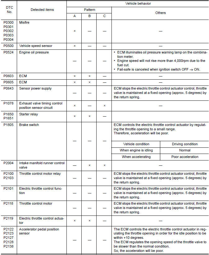
Fail Safe Pattern

Fail Safe List

 System
...
 Multiport fuel injection system
MULTIPORT FUEL INJECTION SYSTEM : System
Description
SYSTEM DIAGRAM
*1: ECM determines the start signal status by the signals of engine speed and
battery voltage.
*2: M/T models
*3: CVT mod ...
Other materials:
B142X Collision detection
Description
DTC B142X COLLISION DETECTION
The air bag diagnosis sensor unit will set this DTC if it has detected a
collision which has resulted in a deployment
of one or more air bags or pre-tensioners. If this DTC is detected after a SRS
repair, the air bag diagnosis
sensor unit has not yet ...
Air flow charts
The following charts show the button and dial
positions for MAXIMUM AND QUICK heating,
cooling or defrosting. The air recirculation
button should always be in the OFF position
for heating and defrosting.
...
Front suspension assembly
Inspection
COMPONENT PART
Check the mounting conditions (looseness, backlash) of each component. Verify
the component conditions
(wear, damage) are normal.
Ball Joint Axial End Play
Set the front wheels in a straight-ahead position.
Hold the axle side of the transverse link, and check th ...
