Nissan Sentra Service Manual: P0138 HO2S2
DTC Logic
DTC DETECTION LOGIC
The heated oxygen sensor 2 has a much longer switching time between rich and lean than the air fuel ratio (A/ F) sensor 1. The oxygen storage capacity of the three way catalyst (manifold) causes the longer switching time.
MALFUNCTION A
To judge the malfunctions of heated oxygen sensor 2, ECM monitors whether the voltage is unusually high during the various driving condition such as fuel-cut.
MALFUNCTION B
To judge the malfunctions of heated oxygen sensor 2, ECM monitors whether the minimum voltage of sensor is sufficiently low during the various driving condition such as fuel-cut.

| DTC No. | CONSULT screen terms (Trouble diagnosis content) | DTC detecting condition | Possible cause | |
| P0138 | HO2S2 (B1) (O2 sensor circuit high voltage bank 1 sensor 2) | A) | An excessively high voltage from the sensor is sent to ECM. |
|
| B) | The minimum voltage from the sensor is not reached to the specified voltage. |
|
||
DTC CONFIRMATION PROCEDURE
1.PRECONDITIONING
If DTC Confirmation Procedure has been previously conducted, always perform the following procedure before conducting the next test.
- Turn ignition switch OFF and wait at least 10 seconds.
- Turn ignition switch ON.
- Turn ignition switch OFF and wait at least 10 seconds.
>> GO TO 2.
2.PERFORM DTC CONFIRMATION PROCEDURE FOR MALFUNCTION A
- Start engine and warm it up to normal operating temperature.
- Turn ignition switch OFF and wait at least 10 seconds.
- Start engine and keep the engine speed between 3,500 and 4,000 rpm for at least 1 minute under no load.
- Let engine idle for 2 minutes.
- Check 1st trip DTC.
Is 1st trip DTC detected? YES >> Proceed to EC-227, "Diagnosis Procedure".
NO-1 (  With CONSULT)>>GO TO 3.
NO-2 ( Without CONSULT)>>GO TO 5.
3.PERFORM DTC CONFIRMATION PROCEDURE FOR MALFUNCTION B
NOTE:
For better results, perform “DTC WORK SUPPORT” at a temperature of 0 to 30°C (32 to 86°F).
- Turn ignition switch ON and select “DATA MONITOR” mode of “ENGINE” using CONSULT.
- Start engine and warm it up to normal operating temperature.
- Turn ignition switch OFF and wait at least 10 seconds.
- Start engine and keep the engine speed between 3,500 and 4,000 rpm for at least 1 minute under no load.
- Let engine idle for 1 minute.
- Make sure that “COOLANT TEMP/S” indication is more than 70°C (158°F).
If not, warm up engine and go to next step when “COOLANT TEMP/S” indication reaches 70°C (158°F).
- Open engine hood.
- Select “HO2S2 (B1) P1146” of “HO2S2” in “DTC WORK SUPPORT” mode of “ENGINE” using CONSULT.
- Follow the instruction of CONSULT.
NOTE:
It will take at most 10 minutes until “COMPLETED” is displayed.
- Touch “SELF-DIAG RESULT”.
Which is displayed on CONSULT
OK >> INSPECTION END
NG >> Proceed to EC-227, "Diagnosis Procedure".
CAN NOT BE DIAGNOSED>>GO TO 4.
4.PERFORM DTC CONFIRMATION PROCEDURE FOR MALFUNCTION B AGAIN
- Turn ignition switch OFF and leave the vehicle in a cool place (soak the vehicle).
- Perform DTC confirmation procedure again.
>> GO TO 3.
5.PERFORM COMPONENT FUNCTION CHECK FOR MALFUNCTION B
Perform component function check. Refer to EC-226, "Component Function Check".
NOTE:
Use component function check to check the overall function of the heated oxygen sensor 2 circuit. During this check, a 1st trip DTC might not be confirmed.
Is the inspection result normal? YES >> INSPECTION END
NO >> Proceed to EC-227, "Diagnosis Procedure".
Component Function Check
1.PERFORM COMPONENT FUNCTION CHECK-1
 Without CONSULT
- Start engine and warm it up to normal operating temperature
- Turn ignition switch OFF and wait at least 10 seconds.
- Start engine and keep the engine speed between 3,500 and 4,000 rpm for at least 1 minute under no load.
- Let engine idle for 1 minute.
- Check the voltage between ECM harness connector and ground as per the following condition.
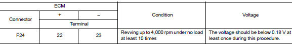
Is the inspection result normal? YES >> INSPECTION END
NO >> GO TO 2.
2.PERFORM COMPONENT FUNCTION CHECK-2
Check the voltage between ECM harness connector and ground as per the following condition.

Is the inspection result normal? YES >> INSPECTION END
NO >> GO TO 3.
3.PERFORM COMPONENT FUNCTION CHECK-3
Check the voltage between ECM harness connector and ground as per the following condition.

Is the inspection result normal? YES >> INSPECTION END
NO >> Proceed to EC-227, "Diagnosis Procedure".
Diagnosis Procedure
1.INSPECTION START
Confirm the detected malfunction (A or B). Refer to EC-225, "DTC Logic".
Which malfunction is detected? A >> GO TO 2.
B >> GO TO 6.
2.CHECK HO2S2 CONNECTOR FOR WATER
- Turn ignition switch OFF.
- Disconnect heated oxygen sensor 2 harness connector.
- Check connectors for water.
Water should not exist.
Is the inspection result normal? YES >> GO TO 3.
NO >> Repair or replace error-detected parts.
3.CHECK HO2S2 GROUND CIRCUIT
- Disconnect ECM harness connector.
- Check the continuity between HO2S2 harness connector and ECM harness connector.

- Also check harness for short to power.
Is the inspection result normal? YES >> GO TO 4.
NO >> Repair or replace error-detected parts.
4.CHECK HO2S2 INPUT SIGNAL CIRCUIT
- Check the continuity between HO2S2 harness connector and ECM harness connector.

- Check the continuity between HO2S2 harness connector and ground, or ECM harness connector and ground.

- Also check harness for short to power.
Is the inspection result normal? YES >> GO TO 5.
NO >> Repair or replace error-detected parts.
5.CHECK HEATED OXYGEN SENSOR 2
Check the heated oxygen sensor 2. Refer to EC-229, "Component Inspection (HO2S2)".
Is the inspection result normal? YES >> Check intermittent incident. Refer to GI-39, "Intermittent Incident".
NO >> Replace heated oxygen sensor 2. Refer to EX-5, "Exploded View".
6.CLEAR THE MIXTURE RATIO SELF-LEARNING VALUE
- Clear the mixture ratio self-learning value. Refer to EC-142, "Work Procedure".
- Run engine for at least 10 minutes at idle speed.
Is the 1st trip DTC P0172 detected? Is it difficult to start engine? YES >> Perform trouble diagnosis for DTC P0172. Refer to EC-250, "DTC Logic".
NO >> GO TO 7.
7.CHECK HO2S2 GROUND CIRCUIT
- Turn ignition switch OFF.
- Disconnect heated oxygen sensor 2 harness connector.
- Disconnect ECM harness connector.
- Check the continuity between HO2S2 harness connector and ECM harness connector.

- Also check harness for short to ground and to power.
Is the inspection result normal? YES >> GO TO 8.
NO >> Repair or replace error-detected parts.
8.CHECK HO2S2 INPUT SIGNAL CIRCUIT
- Check the continuity between HO2S2 harness connector and ECM harness connector.

- Check the continuity between HO2S2 harness connector and ground, or ECM harness connector and ground.

- Also check harness for short to power.
Is the inspection result normal? YES >> GO TO 9.
NO >> Repair open circuit or short to ground or short to power in harness or connectors.
9.CHECK HEATED OXYGEN SENSOR 2
Check the heated oxygen sensor 2. Refer to EC-229, "Component Inspection (HO2S2)".
Is the inspection result normal? YES >> Check intermittent incident. Refer to GI-39, "Intermittent Incident".
NO >> Replace heated oxygen sensor 2. Refer to EX-5, "Exploded View".
Component Inspection (HO2S2)
1.INSPECTION START
Do you have CONSULT? Do you have CONSULT? YES >> GO TO 2.
NO >> GO TO 3.
2.CHECK HEATED OXYGEN SENSOR 2
 With CONSULT
- Turn ignition switch ON and select “DATA MONITOR” mode of “ENGINE” using CONSULT.
- Start engine and warm it up to normal operating temperature.
- Turn ignition switch OFF and wait at least 10 seconds.
- Start engine and keep the engine speed between 3,500 and 4,000 rpm for at least 1 minute under no load.
- Let engine idle for 1 minute
- Select “FUEL INJECTION” in “ACTIVE TEST” mode of “ENGINE” using CONSULT, and select “HO2S2 (B1)” as the monitor item with CONSULT.
- Check “HO2S2 (B1)” at idle speed when adjusting “FUEL INJECTION” to ± 25%.

“HO2S2 (B1)” should be above 0.72 V at least once when the “FUEL INJECTION” is + 25%.
“HO2S2 (B1)” should be below 0.18 V at least once when the “FUEL INJECTION” is − 25%.
Is the inspection result normal? YES >> INSPECTION END
NO >> Replace heated oxygen sensor 2. Refer to EX-5, "Exploded View".
3.CHECK HEATED OXYGEN SENSOR 2-1
 Without CONSULT
- Start engine and warm it up to normal operating temperature.
- Turn ignition switch OFF and wait at least 10 seconds.
- Start engine and keep the engine speed between 3,500 and 4,000 rpm for at least 1 minute under no load.
- Let engine idle for 1 minute.
- Check the voltage between ECM harness connector and ground as per the following condition.

Is the inspection result normal? YES >> INSPECTION END
NO >> GO TO 4.
4.CHECK HEATED OXYGEN SENSOR 2-2
Check the voltage between ECM harness connector and ground as per the following condition.

Is the inspection result normal? YES >> INSPECTION END
NO >> GO TO 5.
5.CHECK HEATED OXYGEN SENSOR 2-3
Check the voltage between ECM harness connector and ground as per the following condition.

Is the inspection result normal? YES >> INSPECTION END
NO >> Replace heated oxygen sensor 2. Refer to EX-5, "Exploded View".
 P0137 HO2S2
DTC Logic
DTC DETECTION LOGIC
The heated oxygen sensor 2 has a much longer switching time
between rich and lean than the air fuel ratio (A/F) sensor 1. The oxygen
storage capacity of the three way ...
 P0139 HO2S2
DTC Logic
DTC DETECTION LOGIC
The heated oxygen sensor 2 has a much longer switching time
between rich and lean than the air fuel ratio (A/F) sensor 1. The oxygen
storage capacity of the three way ...
Other materials:
Removal and installation
Starter motor
Exploded View
“S” terminal harness
“B” terminal harness
Starter motor
Cylinder block
Removal and Installation
NOTE:
When removing components such as hoses, tubes/lines, etc., cap or plug
openings to prevent fluid from spilling.
REMOVAL
Dis ...
Ignition timing
Inspection
1.CHECK IGNITION TIMING
Attach timing light to the ignition coil No.1 harness.
Check ignition timing.
: Timing indicator
Specification : EC-486, "Ignition Timing"
>> INSPECTION END
...
Wiring diagram
Sport mode system
Wiring diagram
...
