Nissan Sentra Service Manual: P0447 EVAP Canister vent control valve
DTC Logic
DTC DETECTION LOGIC
| DTC No. | CONSULT screen terms (Trouble diagnosis content) | DTC detecting condition | Possible cause |
| P0447 | VENT CONTROL VALVE (Evaporative emission system vent control circuit open) | An improper voltage signal is sent to ECM through EVAP canister vent control valve. |
|
DTC CONFIRMATION PROCEDURE
1.PRECONDITIONING
If DTC Confirmation Procedure has been previously conducted, always perform the following procedure before conducting the next test.
- Turn ignition switch OFF and wait at least 10 seconds.
- Turn ignition switch ON.
- Turn ignition switch OFF and wait at least 10 seconds.
TESTING CONDITION:
Before performing the following procedure, confirm battery voltage is more than 11 V at idle.
>> GO TO 2.
2.PERFORM DTC CONFIRMATION PROCEDURE
- Start engine and wait at least 8 seconds.
- Check 1st trip DTC.
Is 1st trip DTC detected? YES >> Proceed to EC-301, "Diagnosis Procedure".
NO >> INSPECTION END
Diagnosis Procedure
1.INSPECTION START
Do you have CONSULT? Do you have CONSULT? YES >> GO TO 2.
NO >> GO TO 3.
2.CHECK EVAP CANISTER VENT CONTROL VALVE CIRCUIT
 With CONSULT
- Turn ignition switch OFF and then turn ON.
- Select “VENT CONTROL/V” in “ACTIVE TEST” mode of “ENGINE” using CONSULT.
- Touch “ON/OFF” on CONSULT screen.
- Check for operating sound of the valve.
Clicking sound should be heard.
Is the inspection result normal? YES >> GO TO 7.
NO >> GO TO 3.
3.CHECK EVAP CANISTER VENT CONTROL VALVE POWER SUPPLY
- Turn ignition switch OFF.
- Disconnect EVAP canister vent control valve harness connector.
- Turn ignition switch ON.
- Check the voltage between EVAP canister vent control valve harness connector and ground.

Is the inspection result normal? YES >> GO TO 5.
NO >> GO TO 4.
4.CHECK EVAP CANISTER VENT CONTROL VALVE POWER SUPPLY CIRCUIT
Turn ignition switch OFF.
Disconnect IPDM E/R harness connector.
Check the continuity between EVAP canister vent control valve harness connector and IPDM E/R harness connector.

- Also check harness for short to ground.
Is the inspection result normal? YES >> Perform the trouble diagnosis for power supply circuit.
NO >> Repair or replace error-detected parts.
5.CHECK EVAP CANISTER VENT CONTROL VALVE OUTPUT SIGNAL CIRCUIT
- Turn ignition switch OFF.
- Disconnect ECM harness connector.
- Check the continuity between EVAP canister vent control valve harness connector and ECM harness connector.

- Also check harness for short to power.
Is the inspection result normal? YES >> GO TO 6.
NO >> Repair or replace error-detected parts.
6.CHECK RUBBER TUBE FOR CLOGGING
- Disconnect rubber tube connected to EVAP canister vent control valve.
- Check the rubber tube for clogging.
Is the inspection result normal? YES >> GO TO 7.
NO >> Clean the rubber tube using an air blower.
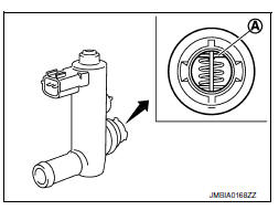
7.CHECK EVAP CANISTER VENT CONTROL VALVE
Check the EVAP canister vent control valve. Refer to EC-303, "Component Inspection".
Is the inspection result normal? YES >> Check intermittent incident. Refer to GI-39, "Intermittent Incident".
NO >> Replace EVAP canister vent control valve. Refer to FL-15, "Removal and Installation"
Component Inspection
1.CHECK EVAP CANISTER VENT CONTROL VALVE-1
- Turn ignition switch OFF.
- Remove EVAP canister vent control valve from EVAP canister.
- Check portion
 of EVAP
canister vent control valve for being rusted.
Is it rusted? YES >> Replace EVAP canister vent control valve. Refer to FL- 15, "Removal and Installation".
NO >> GO TO 2.
2.CHECK EVAP CANISTER VENT CONTROL VALVE-2
 With CONSULT
- Reconnect harness connectors disconnected.
- Turn ignition switch ON.
- Perform “VENT CONTROL/V” in “ACTIVE TEST” mode of “ENGINE” using CONSULT.
- Check air passage continuity and operation delay time.
Make sure new O-ring is installed properly.


Operation takes less than 1 second.
 Without CONSULT
Check air passage continuity and operation delay time under the following conditions.
Make sure new O-ring is installed properly.

Operation takes less than 1 second.
Is the inspection result normal? YES >> GO TO 3.
NO >> Replace EVAP canister vent control valve. Refer to FL-15, "Removal and Installation".
3.CHECK EVAP CANISTER VENT CONTROL VALVE-3
 With CONSULT
- Clean the air passage [portion
![] of EVAP canister vent](images/books/349/13/index126.gif) to
to
 ] of EVAP canister vent
control valve using an air blower. - Perform “VENT CONTROL/V” in “ACTIVE TEST” mode of “ENGINE” using CONSULT.
- Check air passage continuity and operation delay time.
Make sure new O-ring is installed properly.

Operation takes less than 1 second.

 Without CONSULT
- Clean the air passage [portion
to
] of EVAP canister vent
control valve using an air blower. - Check air passage continuity and operation delay time under the following conditions.
Make sure new O-ring is installed properly.

Operation takes less than 1 second.
Is the inspection result normal? YES >> INSPECTION END
NO >> Replace EVAP canister vent control valve. Refer to FL-15, "Removal and Installation".
 P0444, P0445 EVAP Canister purge volume control solenoid valve
DTC Logic
DTC DETECTION LOGIC
DTC No.
CONSULT screen terms
(Trouble diagnosis content)
DTC detecting condition
Possible cause
P0444
PURG VOLUME CONT/V
(Evaporative ...
 P0448 EVAP Canister vent control valve
DTC Logic
DTC DETECTION LOGIC
DTC No.
CONSULT screen terms
(Trouble diagnosis content)
DTC detecting condition
Possible cause
P0448
VENT CONTROL VALVE
(Evaporative ...
Other materials:
Condenser
Removal and installation
Removal
Remove the rear pillar finisher. Refer to INT-29, "REAR PILLAR FINISHER
: Removal and Installation".
Disconnect the harness connectors (1), remove the condenser
bolt (A) and the condenser (2).
: Front
Installation
Installation is in th ...
Anti-lock Braking System (ABS)
WARNING
The Anti-lock Braking System (ABS) is a
sophisticated device, but it cannot prevent
accidents resulting from careless
or dangerous driving techniques. It can
help maintain vehicle control during
braking on slippery surfaces. Remember
that stopping distances ...
Special Service Tool
The actual shapes of Kent-Moore tools may differ from those of special
service tools illustrated here.
CAUTION:
Every time the vehicle is lifted up, maintain the complete vehicle
curb condition.
Since the vehicle's center of gravity changes when removing main
parts on the front si ...
