Nissan Sentra Service Manual: P1800 Intake manifold tuning valve
DTC Logic
DTC DETECTION LOGIC
| DTC No. | CONSULT screen terms (Trouble diagnosis content) | DTC detecting condition | Possible cause |
| P1800 | VIAS S/V-1 (Variable intake air system control solenoid valve-1) | An excessively low or high voltage signal is sent to ECM through the intake manifold tuning valve. |
|
DTC CONFIRMATION PROCEDURE
1.CONDITIONING
If DTC Confirmation Procedure has been previously conducted, always perform the following before conducting the next test.
- Turn ignition switch OFF and wait at least 10 seconds.
- Turn ignition switch ON.
- Turn ignition switch OFF and wait at least 10 seconds.
TESTING CONDITION:
Before performing the following procedure, confirm battery voltage is more than 11 V at idle.
>> GO TO 2.
2.PERFORM DTC CONFIRMATION PROCEDURE
- Start engine and warm it up to the normal operating temperature. [more than 60В°C (140В°F)]
- Let it idle for at least 10 seconds. (engine speed: less than 1,000 rpm)
- Check 1st trip DTC.
Is 1st trip DTC detected? YES >> Proceed to EC-408, "Diagnosis Procedure".
NO >> INSPECTION END
Diagnosis Procedure
1.CHECK INTAKE MANIFOLD TUNING VALVE MOTOR POWER SUPPLY
- Turn ignition switch ON.
- Check the voltage between ECM harness connector.

Is the inspection result normal? YES >> GO TO 3.
NO >> GO TO 2.
2.CHECK INTAKE MANIFOLD TUNING VALVE MOTOR POWER SUPPLY CIRCUIT
- Turn ignition switch OFF.
- Disconnect ECM harness connector.
- Disconnect IPDM E/R harness connector.
- Check the continuity between ECM harness connector and IPDM E/R harness connector.

- Also check harness for short to ground.
Is the inspection result normal? YES >> Perform the trouble diagnosis for power supply circuit.
NO >> Repair or replace error-detected parts.
3.CHECK INTAKE MANIFOLD TUNING VALVE MOTOR OUTPUT SIGNAL CIRCUIT
- Disconnect intake manifold tuning valve motor harness connector
- Check the continuity between intake manifold tuning valve motor harness connector and ECM harness connector.
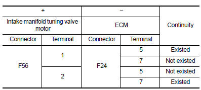
- Also check harness for short to ground and to power.
Is the inspection result normal? YES >> GO TO 4.
NO >> Repair or replace error-detected parts.
4.CHECK INTAKE MANIFOLD TUNING VALVE MOTOR
Check the intake manifold tuning valve motor. Refer to EC-409, "Component Inspection (Intake Manifold Tuning Valve)".
Is the inspection result normal? YES >> Check intermittent incident. Refer to GI-39, "Intermittent Incident".
NO >> Replace intake manifold assembly. Refer to EM-27, "Removal and Installation".
Component Inspection (Intake Manifold Tuning Valve)
1.CHECK INTAKE MANIFOLD TUNING VALVE MOTOR
- Turn ignition switch OFF.
- Disconnect intake manifold tuning valve motor harness connector.
- Check the resistance between intake manifold tuning valve motor terminals as per the following.

Is the inspection result normal? YES >> INSPECTION END
NO >> Replace intake manifold. Refer to EM-27, "Removal and Installation".
 P1715 Input speed sensor
Description
ECM receives input speed sensor signal from TCM through CAN communication
line. ECM uses this signal for
engine control.
DTC Logic
DTC DETECTION LOGIC
NOTE:
If DTC P1715 is disp ...
 P1805 Brake switch
DTC Logic
DTC DETECTION LOGIC
DTC No.
CONSULT screen terms
(Trouble diagnosis content)
DTC detecting condition
Possible cause
P1805
BRAKE SW/CIRCUIT
(Brake switch c ...
Other materials:
Wiring diagram
Power distribution system
Wiring diagram
...
Can communication circuit
Diagnosis procedure
1.Connector inspection
Turn the ignition switch OFF.
Disconnect the battery cable from the negative terminal.
Disconnect all the unit connectors on can communication system.
Check terminals and connectors for damage, bend and loose connection.
Is the inspection resu ...
System description
Component parts
Body control system
Body control system : component parts location
BCM (view with instrument panel removed)
Combination switch reading system
Combination switch reading system : component parts location
BCM (view with combination meter
removed)
Combination s ...
