Nissan Sentra Service Manual: System
System Diagram

System Description
FRONT WIPER CONTROL (BASIC)
- BCM detects the combination switch position by the combination switch reading function.
- BCM transmits the front wiper request signal to the IPDM E/R using CAN communication.
- IPDM E/R controls the integrated front wiper relay and front wiper high relay based on the status of the front wiper request signal.
- IPDM E/R provides power to operate the front wiper motor.
LOW SPEED OPERATION
- Ignition switch ON.
- Front wiper switch in LO or MIST position.
- BCM reads the combination switch position and transmits the front wiper request signal (LO) to IPDM E/R using CAN communication.
- IPDM E/R turns ON the front wiper relay.
HIGH SPEED OPERATION
- Ignition switch ON.
- Front wiper switch in HI.
- BCM reads the combination switch position and transmits the front wiper request signal (HI) to IPDM E/R using CAN communication
- IPDM E/R turns ON the front wiper relay and the front wiper high relay.
INTERMITTENT OPERATION
- Ignition switch ON.
- Front wiper switch INT.
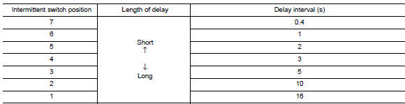
- BCM reads the combination switch position. BCM calculates the delay interval based on the table below and then transmits the front wiper request signal (INT) to IPDM E/R using CAN communication.
- IPDM E/R turns ON the front wiper relay only once.
- BCM detects stop position of the front wiper motor based on the front wiper stop position signal received from the IPDM E/R.
- BCM transmits the front wiper request signal (INT) again after the delay interval.

AUTO STOP OPERATION
- Front wiper switch is turned OFF.
- BCM monitors wiper switch position by combination switch reading position function.
- BCM stops transmitting the front wiper request signal to the IPDM E/R.
- IPDM E/R detects the front wiper auto stop signal from the position of the front wiper motor (stop position/ except stop position).
- When the front wiper request signal is stopped, IPDM E/R turns ON the front wiper relay until the front wiper motor returns to the stop position
- IPDM E/R turns the front wiper relay OFF when the front wiper motor has reached the stop position.

MIST OPERATION
- Ignition switch ON.
- Front washer switch in OFF position.
- Front wiper switch in MIST position.
- BCM reads the combination switch position and transmits the front wiper request signal (LO) to IPDM E/R using CAN communication.
- IPDM E/R turns ON the front wiper relay.
- The front wiper operates once after the front washer operation.
WIPER/WASHER OPERATION
- Ignition switch ON.
- Front washer switch ON.
- The front washer switch provides ground for the front washer motor.
- BCM reads the combination switch position and transmits the front wiper request signal (LO) to IPDM E/R using CAN communication.
- BCM transmits the front wiper request signal (LO) to IPDM E/R using CAN communication.
- IPDM E/R turns ON the front wiper relay.
- The front wiper operates.
NOTE:
BCM transmits the front wiper request signal (LO) so that the front wiper operates approximately 3 times after front washer switch OFF is detected.
Fail-Safe
FAIL−SAFE OPERATION
IPDM E/R performs the fail-safe function when the front wiper auto stop circuit is malfunctioning. Refer to PCS-19, "Fail-safe" (with Intelligent Key system) or PCS-47, "Fail-Safe" (without Intelligent Key system).
 Front wiper and washer system
Component Parts Location
BCM (view under instrument panel,
left side of vehicle)
Combination meter
IPDM E/R (view with air inlet duct
removed)
Combination switch (wiper and
washer ...
 Diagnosis system (bcm) (with intelligent key system)
Common item
Common item : consult function (bcm - common item)
APPLICATION ITEM
CONSULT performs the following functions via CAN communication with BCM.
SYSTEM APPLICATION
BCM can perform the ...
Other materials:
Diagnosis system (TCM)
DIAGNOSIS DESCRIPTION
DIAGNOSIS DESCRIPTION : 1 Trip Detection Diagnosis and 2 Trip Detection
Diagnosis
NOTE:
“Start the engine and turn OFF the ignition switch after warm-up.” This is
defined as 1 trip.
TRIP DETECTION DIAGNOSIS
When initial malfunction is detected, TCM mem ...
Wiring diagram
Nvis (nissan vehicle immobilizer system-
nats)
Wiring Diagram
Vehicle security system
Wiring diagram
...
Automatic operation
Heating (A/C OFF)
The air conditioner does not activate. When you
need to heat only, use this mode.
Press the A/C button. (A/C OFF will be
displayed and A/C indicator will turn off.)
Use the temperature control buttons to set
the desired temperature.
The temperature of the passenge ...
